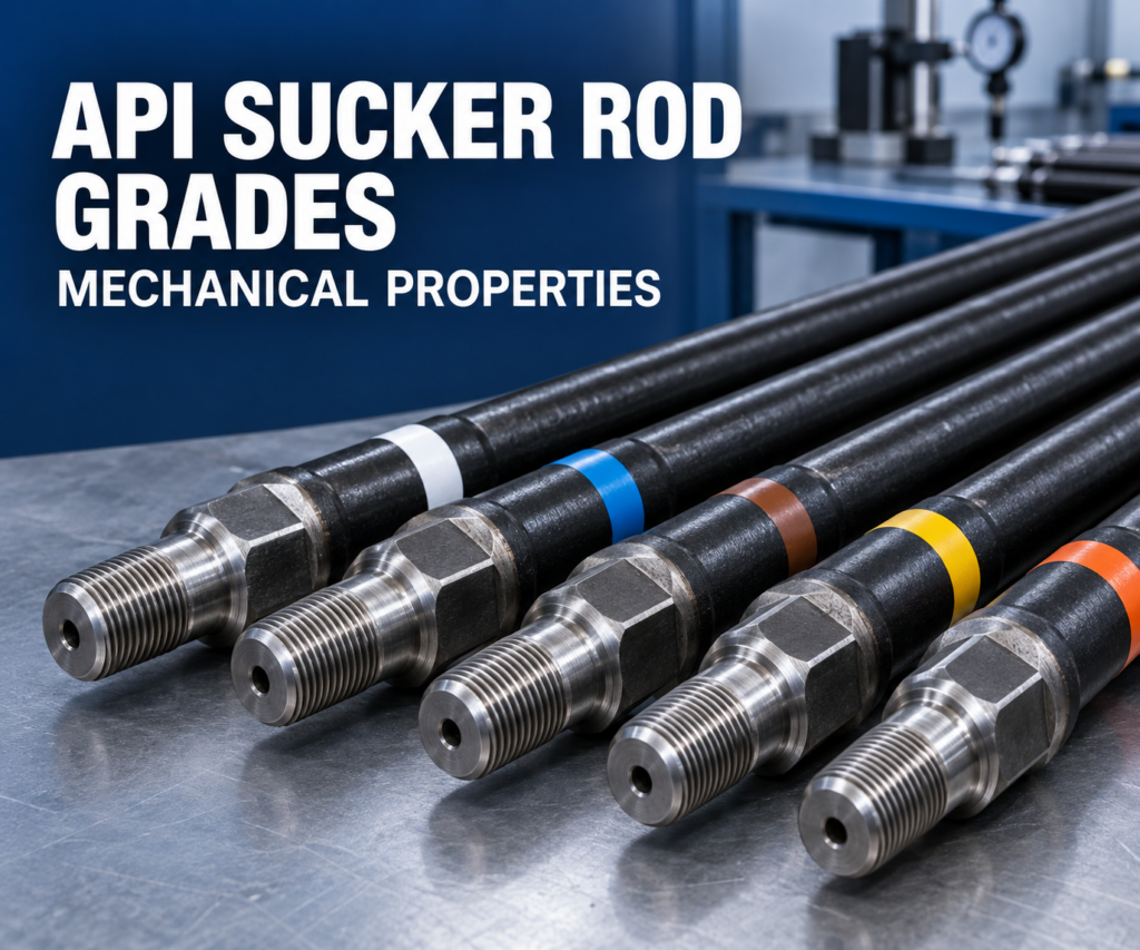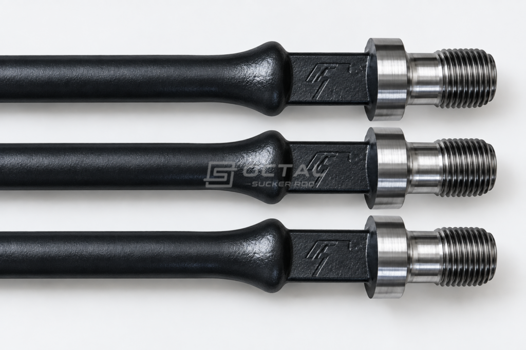
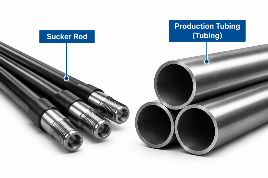
Sucker rods are steel or other engineered rod components connected to form a rod string that transfers reciprocating motion from the surface pumping unit to the downhole pump. Sucker rod couplings join individual rods through threaded connections, while production tubing provides the flow path for produced fluids from the downhole pump to the surface. These components operate together inside the well, with the rod string moving up and down within the stationary or anchored tubing.
A deviated well is drilled along a wellbore trajectory that departs from vertical to reach a designated underground target. Unlike a straight vertical well, its inclination and direction may change along the measured depth, creating build-up sections, hold sections, and localized changes in wellbore curvature. These geometric conditions affect how the sucker rod string sits and moves inside the tubing. Gravity, rod-string stiffness, and lateral forces can cause the rods and couplings to move toward the tubing wall.
During repeated pumping cycles, contact between the moving rod string and the tubing can generate friction and sliding wear. Sucker rod couplings are particularly important contact points because their outside diameter is larger than that of the rod body, leaving less radial clearance inside the tubing. Repeated coupling-to-tubing contact can cause localized wear, reduce tubing wall thickness, and eventually lead to tubing leakage.
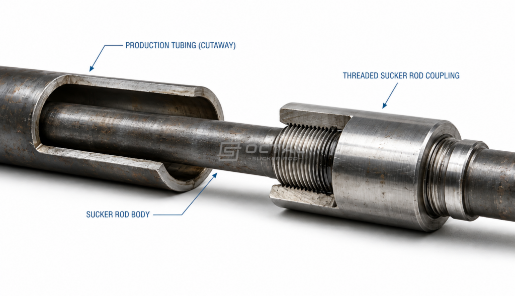
The severity of this wear depends on wellbore trajectory, contact load, coupling dimensions, surface properties, pumping conditions, and the use of rod guides. Understanding these factors helps identify why tubing wear develops in deviated wells and which engineering measures can reduce damage to both sucker rod components and production tubing.
Why Does Rod-Tubing Contact Occur in Deviated Wells?
In a vertical well, the sucker rod string generally follows the tubing axis under normal operating conditions. In a deviated well, the wellbore changes direction, and the rod string is affected by gravity, bending forces, and lateral contact forces.
As the pumping unit moves the rod string up and down, these forces can cause the rods and couplings to contact the inner wall of the production tubing.
Several factors contribute to this contact.
Wellbore Deviation and Dogleg Severity
Wellbore deviation describes the inclination of the well from vertical, while Dogleg Severity (DLS) measures the rate of change in wellbore direction over a specified measured depth.
A build section, hold section, or localized dogleg can change the direction of the rod string and increase its tendency to contact the tubing wall.The location and severity of contact depend on more than the inclination angle alone. Wellbore curvature, rod-string stiffness, rod weight, pumping conditions, and tubing configuration also influence the contact forces.
For this reason, deviation survey data should be considered when evaluating rod-tubing wear, particularly in wells with repeated tubing failures at specific measured depths.
Side Loading and Rod String Deflection
The weight of the sucker rod string acts vertically, while the tubing follows the wellbore trajectory. In an inclined section, the resulting force distribution can push the rod string toward one side of the tubing.
This creates Side Loading, which increases the normal contact force between the rod string and tubing wall.
When the rod string moves during each pumping cycle, the contact position and frictional forces may change along the wellbore.
The resulting contact can involve:
- Sucker rod body against tubing wall.
- Sucker rod coupling against tubing wall.
- Rod guide against tubing wall.
The coupling often becomes a major wear contact point because of its larger outside diameter and relatively concentrated contact area.
Rod String Buckling and Tubing Movement
Rod string buckling can further increase rod-tubing contact, particularly when the rod string experiences compression during the downstroke.
Tubing movement also affects the available clearance. In an unanchored tubing string, changes in axial loading during pumping can cause tubing movement or buckling under certain operating conditions.
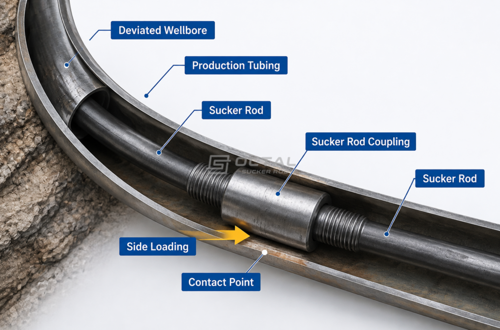
When rod-string deflection and tubing movement occur together, contact conditions may become more severe.A study presented at the Southwestern Petroleum Shortcourse identifies deviated wellbores, sucker rod buckling on the downstroke, and tubing buckling on the upstroke as important causes of rod-induced tubing wear. Its engineering approach uses deviation survey data and rod-by-rod force calculations to evaluate wear locations.
Well deviation should also be considered when selecting the rod grade and string configuration. Our guide to API 11B sucker rod selection for different oil well conditions explains how well depth, loading conditions, corrosion and deviation affect rod selection.
How Do Sucker Rod Couplings Cause Tubing Wear?
Sucker rod couplings connect individual rods into a continuous rod string. Each coupling contains internal threads that engage the threaded pin ends of adjacent rods.
During operation, the coupling moves with the rod string inside the production tubing. When the rod string is deflected toward the tubing wall, the coupling can become the primary contact point.
The relationship between coupling geometry, contact load, and surface characteristics determines how wear develops.
Coupling Outside Diameter and Tubing Clearance
Sucker rod couplings have a larger outside diameter than the rod body. This means the space between the coupling and the inner wall of the production tubing is smaller than the space around the rod body.
The available clearance depends on two dimensions: the inside diameter of the production tubing and the outside diameter of the coupling. The difference between these dimensions represents the total diametral clearance. When the coupling is positioned at the center of the tubing, this clearance is distributed between the two sides.
For example, if the tubing has an inside diameter of 62 mm and the coupling has an outside diameter of 38 mm, the total clearance is 24 mm, or 12 mm on each side when centered.
In deviated wells, the rod string may shift toward one side of the tubing due to gravity, wellbore curvature, and lateral forces. As the available clearance decreases, the coupling can make contact with the tubing wall. Repeated contact during pumping may cause wear on both surfaces.
Slim-hole couplings have a smaller outside diameter than standard full-size couplings, leaving more clearance inside the tubing. They may help reduce contact in restricted-clearance conditions, but their connection strength and dimensional compatibility must still meet the required specifications.
Reciprocating Motion and Contact Friction
During each pumping cycle, sucker rod couplings move upward and downward while remaining inside the production tubing.
When a coupling contacts the tubing wall, repeated sliding movement generates friction at the contact interface.
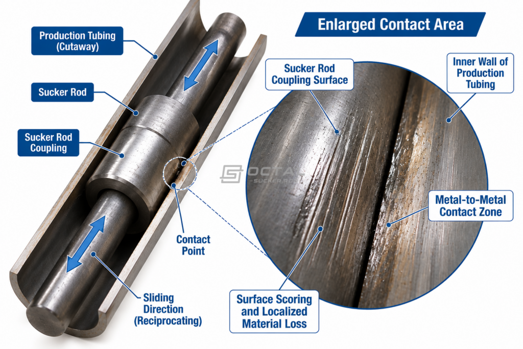
The resulting wear depends on several interacting factors:
- Contact Load: Higher contact forces can increase local contact pressure and material loss.
- Stroke Rate: Pumping speed affects the frequency of contact movement and accumulated sliding cycles.
- Surface Roughness: Surface irregularities can influence friction and abrasive interaction.
- Material Hardness: The hardness relationship between the coupling and tubing affects surface deformation and wear behavior.
- Wellbore Fluid: Produced fluids and suspended solids can change friction, abrasion, and corrosion conditions.
The available clearance also depends on the coupling configuration. Compare sucker rod coupling types and dimensions to understand how full-size and slim-hole designs affect the space available inside production tubing.
Coupling Surface Hardness, Roughness, and Coefficient of Friction
The coupling surface plays an important role in determining how much damage occurs during contact with the tubing wall.
Three properties deserve particular attention.
| Surface Property | Effect on Contact Wear |
| Surface Hardness | Influences resistance to deformation and abrasive wear at the contact interface |
| Surface Roughness | Affects the initial contact condition and frictional behavior |
| Coefficient of Friction | Influences the friction force generated during sliding contact |
Higher coupling hardness does not automatically mean lower tubing wear. The hardness and surface characteristics of both contacting components must be considered together.
A coupling with a hard but rough contact surface may still cause significant wear to the tubing. Similarly, a surface treatment that reduces friction may improve the contact condition without necessarily eliminating material loss.
How Does Tubing Wear Develop in Deviated Wells?
Tubing wear develops gradually as sucker rod couplings repeatedly contact the inner wall of the production tubing. Depending on contact load, sliding conditions, and wellbore environment, the damage can progress from surface marks to localized wall thinning and eventually tubing leakage.
Common Tubing Wear Conditions
| Wear Condition | Description | Potential Consequences |
| Surface Scoring | Repeated coupling contact leaves scratches and wear marks on the tubing inner surface. | Progressive surface damage |
| Localized Grooving | Continuous contact at the same location creates grooves along the tubing wall. | Localized material loss |
| Wall Thickness Reduction | Repeated friction removes tubing material and reduces the remaining wall thickness. | Reduced pressure-bearing capacity |
| Through-Wall Damage | Severe wear penetrates the tubing wall. | Tubing leakage and loss of pressure integrity |
Where Does Tubing Wear Usually Occur?
Tubing wear is often concentrated at sections where wellbore curvature and rod-string movement create repeated contact. Build sections and localized doglegs may be potential wear locations, particularly when side loading is significant.
Comparing recovered tubing damage with well deviation surveys, rod-string configuration, and operating records helps identify the likely contact locations and underlying causes.
What Happens When Tubing Wear Becomes Severe?
When the remaining tubing wall can no longer withstand the operating pressure, a through-wall opening may develop. This can result in:
- Loss of tubing pressure integrity.
- Communication between the tubing and annular space.
- Reduced pumping efficiency.
- Unplanned workover operations and production downtime.
Can Sucker Rod Guides Reduce Tubing Wear?
Sucker rod guides are used to reduce direct contact between sucker rod couplings and production tubing, particularly in deviated wells where rod-string deflection increases the risk of tubing wear.
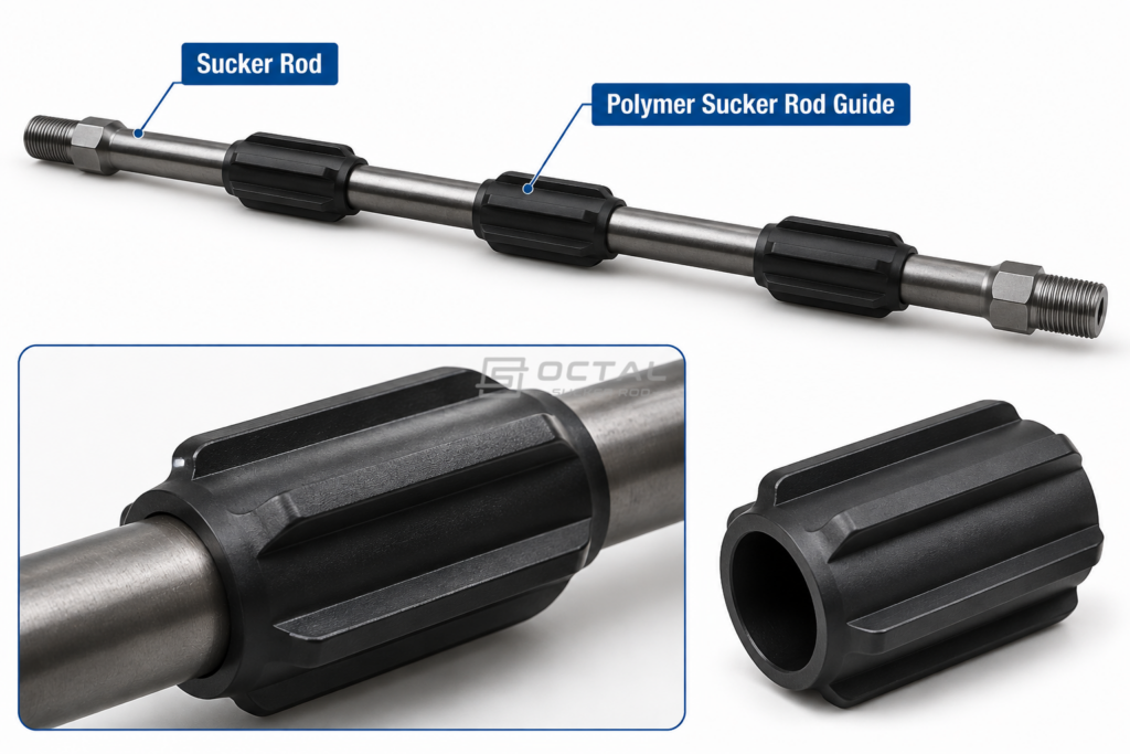
Installed along the sucker rod string, these guides create an intermediate contact surface between the rod assembly and tubing wall. When lateral movement brings the rod string close to the tubing, the guide can contact the tubing before the steel coupling does, helping reduce direct metal-to-metal friction.
How Sucker Rod Guides Control Contact and Wear
During pumping, the sucker rod string moves up and down inside the production tubing. In deviated sections, lateral forces can push the rod string toward the tubing wall. Without a guide, the steel coupling may repeatedly slide against the tubing, gradually removing material from its inner surface.
A rod guide changes this contact condition by placing a wear-resistant component between the coupling and tubing. The guide absorbs the sliding contact and helps limit localized wear on the tubing wall.
However, the guide itself is exposed to continuous friction. Its material and construction therefore need to withstand the actual downhole conditions.
Sucker Rod Guide Materials and Designs
Most sucker rod guides use polymer materials because they can provide suitable sliding properties and wear resistance in rod-tubing contact applications. Depending on the installation method, common designs include:
| Guide Design | Construction | Main Characteristics |
| Molded-On Guides | Polymer molded directly onto the sucker rod | Fixed position and integrated construction |
| Field-Installable Guides | Installed onto the rod at the wellsite | Installation position can be selected according to the rod-string configuration |
The choice of guide material depends on downhole temperature, fluid chemistry, contact load, and expected wear conditions. A suitable material must maintain its shape and mechanical properties during repeated contact with the tubing wall.
Sucker Rod Guide Placement and Spacing
Rod guide placement should be based on wellbore trajectory and side loading. Sections with significant curvature or higher calculated contact forces may require closer guide spacing.
The main factors include well inclination, dogleg severity, rod-string dimensions, and pumping conditions. Guide spacing should be determined by the actual well conditions and rod-string force analysis rather than a fixed interval.
Rod Guide Wear Inspection and Maintenance
Rod guides are exposed to repeated sliding contact and gradually wear during operation. During rod retrieval or workover, inspect them for:
During rod retrieval or workover operations, recovered guides should be inspected for:
- Uneven surface wear.
- Reduced outside diameter.
- Cracks or broken sections.
- Loose or damaged attachments.
Worn guides may no longer protect the tubing from direct coupling contact and should be evaluated for replacement.
How Can Sucker Rod Coupling and Tubing Wear Be Reduced?
Reducing rod-tubing wear requires controlling both coupling contact and rod-string movement. The following measures can help reduce friction, protect tubing surfaces, and limit premature component damage.
Recommended Wear-Reduction Measures
| Measure | Main Considerations | Purpose |
| Slim-Hole Couplings | Smaller outside diameter while maintaining required connection strength | Increase tubing clearance |
| Wear-Resistant Coatings | Suitable coating hardness, adhesion, and friction properties | Reduce coupling surface wear and friction |
| Sucker Rod Guides | Appropriate guide material, position, and spacing | Reduce direct metal-to-metal contact |
| Rod String Optimization | Rod dimensions, loading, and compression conditions | Reduce excessive deflection and side loading |
| Tubing Configuration | Tubing movement, anchoring, and internal condition | Improve rod-tubing operating conditions |
Coupling and Surface Treatment Selection
For wells with recurring tubing wear, coupling outside diameter, material properties, and surface condition should be reviewed together. A smaller coupling may increase radial clearance, while a suitable surface treatment can help reduce friction during contact.
However, connection strength and dimensional compatibility must not be compromised when selecting a different coupling design or surface treatment.
Monitor Wear During Operation
Recovered couplings, rod guides, and tubing should be inspected during workover operations. Comparing their wear patterns and damage locations with previous inspection records helps determine whether the selected wear-control measures are effective.
How Is Rod-Tubing Wear Identified During Inspection?
Rod-tubing wear is usually identified during rod retrieval, tubing inspection, or workover operations. Both the rod assembly and production tubing should be examined to determine the location and extent of damage.
Sucker Rod and Coupling Inspection
Inspect the rod body and couplings for diameter reduction, surface grooves, scratches, scoring, and coating damage. Localized wear on the coupling outside surface may indicate repeated contact with the tubing wall.
Production Tubing Inspection
Check the tubing’s internal surface for wear marks, grooves, wall thinning, and through-wall damage. Wall thickness measurements can help determine the remaining material and identify sections requiring further evaluation.
Wear Location Analysis
Compare the damaged components with wellbore deviation surveys, rod-string configuration, and previous workover records. This helps identify where repeated contact occurs and whether the wear is related to wellbore curvature, side loading, or coupling-to-tubing contact.
FAQ
Why do sucker rod couplings wear production tubing?
Sucker rod couplings can contact the tubing wall when the rod string deflects in deviated sections. Repeated reciprocating movement under contact load creates friction and removes material from the tubing’s internal surface.
Does a higher dogleg severity always cause more tubing wear?
No. Dogleg severity is one factor affecting rod-tubing contact. Actual wear also depends on rod-string stiffness, side loading, coupling dimensions, tubing configuration, pumping conditions, and guide placement.
Can slim-hole couplings reduce tubing wear?
Slim-hole couplings provide additional radial clearance because of their reduced outside diameter. They may reduce contact exposure in restricted tubing conditions, but actual wear reduction depends on well geometry, contact forces, and coupling surface properties.
Do polymer sucker rod guides eliminate rod-tubing wear?
No. Rod guides can reduce direct metal-to-metal contact, but they also experience wear and may lose their protective function over time. Their performance depends on material selection, installation position, side loading, and operating conditions.
What causes a hole in production tubing in a deviated well?
Repeated mechanical contact between sucker rod couplings and tubing can gradually remove tubing wall material. Corrosion and abrasive particles may accelerate the damage. Inspection of the tubing, couplings, and wellbore trajectory is necessary to confirm the failure mechanism.