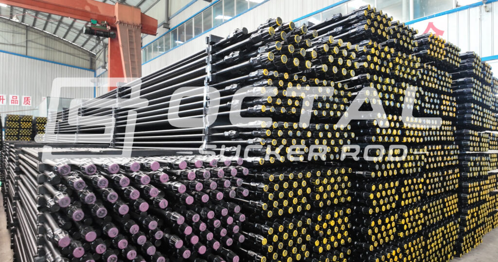
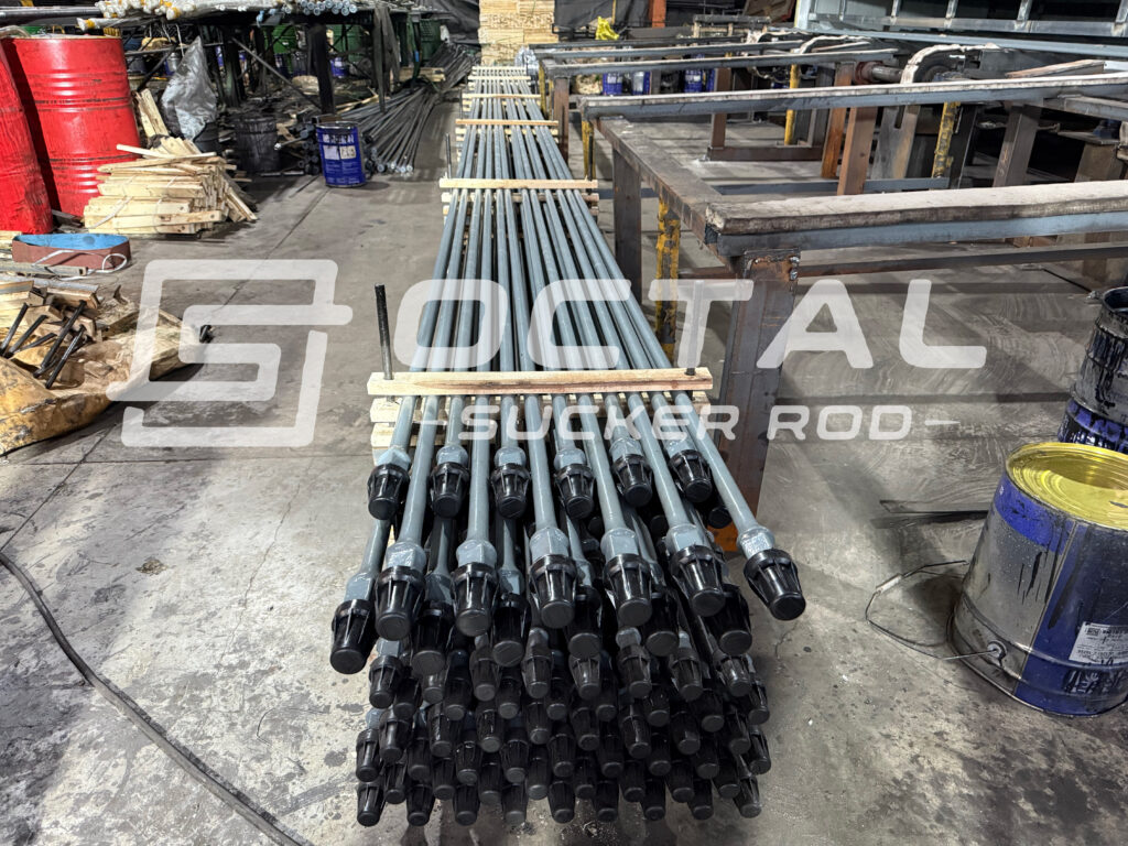
AISI 4130 sucker rod transmits reciprocating motion and axial load from the surface pumping unit to the downhole pump through a solid chromium-molybdenum steel body, forged upset ends, wrench squares, load shoulders and threaded pins. Conventional API-compatible sizes cover nominal body diameters from 5/8 to 1 1/8 in. (15.88–28.58 mm), with standard full-length options of 25 or 30 ft (7.62 or 9.14 m). Separate steel couplings connect the rods into a continuous load-carrying string.
The 4130 steel designation specifies a nominal carbon range of 0.28–0.33%, chromium of 0.80–1.10% and molybdenum of 0.15–0.25%. When manufactured and qualified to the applicable API Grade DA requirements, the finished steel sucker rod must reach at least 85,000 psi (586 MPa) yield strength and 115,000 psi (793 MPa) tensile strength. These values are finished-product acceptance minimums rather than allowable working stresses; actual rod-string design must also account for cyclic loading, connection geometry, wear, corrosion and well deviation.
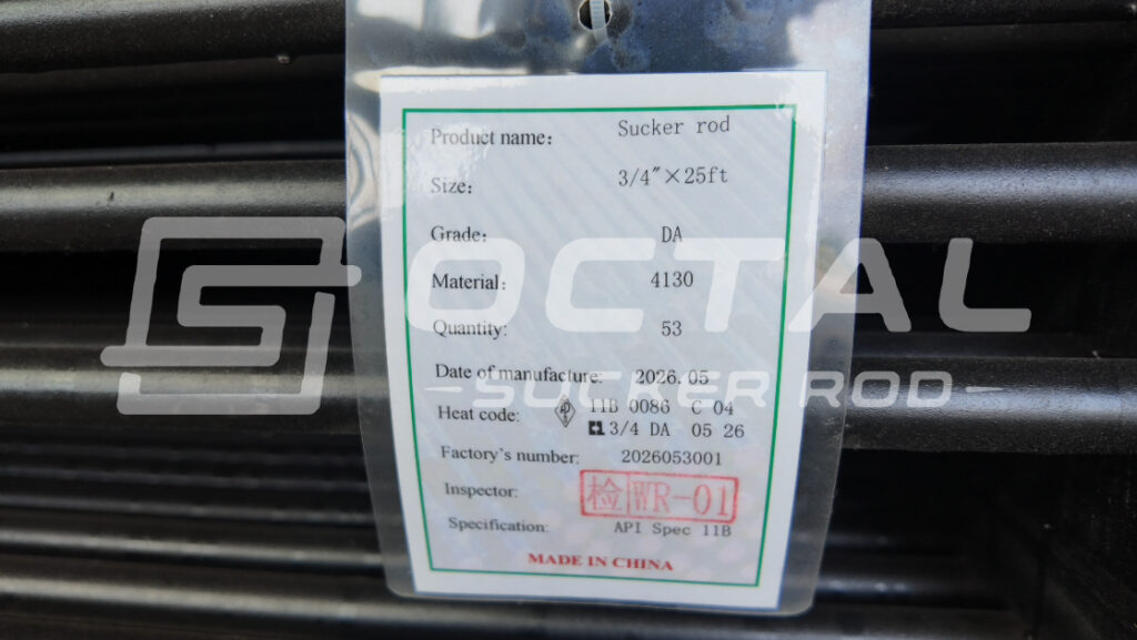
Octal Sucker Rod provides AISI 4130 sucker rods in API-compatible dimensions with matched couplings, heat-number traceability and finished-condition test documentation specified for the order. The technical data below separates material chemistry, finished-grade minimums and calculated load references so that engineers and procurement teams can verify what the supplied rod is qualified to achieve.
Product Definition and Technical Scope
Joined through steel couplings, the individual rods form a string that carries its own submerged weight together with fluid load, pump load and acceleration forces. Deviated well sections can add bending and rod-to-tubing contact to this axial load. Because the stress changes through every pumping cycle, fatigue performance and connection condition matter as much as a single tensile-test result.
The following table defines the normal supply basis for an AISI 4130 product. The purchase order should identify the applicable edition of every standard and any project-specific supplementary requirement.
| Product parameter | Standard supply basis | Engineering meaning |
|---|---|---|
| Rod-body material | SAE/AISI 4130, UNS G41300 | Chromium-molybdenum low-alloy steel chemistry |
| Product standard | API Specification 11B, purchaser-specified applicable edition | Controls finished rod dimensions, grades, connections, inspection, marking and related requirements |
| Applicable API material family | Grade DA alloy route when all finished-grade requirements are met | Current API grade classification includes UNS G41XX0 series steels |
| Construction | Solid rod body with forged ends, wrench squares, shoulders and pin threads | Transfers cyclic axial load through a jointed rod string |
| Common nominal body diameters | 5/8, 3/4, 7/8, 1 and 1 1/8 in. | Diameter controls body area, mass and nominal axial stress |
| Common nominal rod lengths | 25 and 30 ft | Standard field handling and string-length increments |
| Connection method | Matched sucker-rod couplings and API-compatible pin connections | Connection size, shoulder condition and makeup procedure must be coordinated |
| Required traceability | Heat number, production lot, finished test lot and rod marking | Links raw material, processing, inspection and delivered rods |
Material Chemistry and Metallurgical Function
SAE/AISI 4130 belongs to the 41XX chromium-molybdenum alloy family. Carbon provides the base response to heat treatment, chromium increases hardenability, and molybdenum supports through-section strength and reduces the tendency toward temper embrittlement. This combination gives 4130 steel a useful balance of strength, ductility and processability for forged, heat-treated rod components.
The table below presents the standard chemistry range normally associated with UNS G41300. The certified heat analysis remains the acceptance record for each production heat.
| Element | Typical SAE/AISI 4130 range, mass % | Function in the rod body |
|---|---|---|
| Carbon, C | 0.28–0.33 | Governs heat-treatment response, strength and hardness potential |
| Manganese, Mn | 0.40–0.60 | Supports hardenability and deoxidation |
| Silicon, Si | 0.15–0.35 | Acts as a deoxidizer and contributes to strength |
| Chromium, Cr | 0.80–1.10 | Improves hardenability and strength response |
| Molybdenum, Mo | 0.15–0.25 | Supports through-section hardenability and tempering response |
| Phosphorus, P | 0.035 max. | Controlled residual because excessive content can reduce toughness |
| Sulfur, S | 0.040 max. | Controlled residual because excessive content can impair ductility and fatigue performance |
| Iron, Fe | Balance | Base metal |
These limits identify the alloy; they do not prove the condition of the finished rod. A chemical analysis cannot replace tensile testing, dimensional inspection or connection gauging. Likewise, generic 4130 steel properties taken from an annealed bar, normalized plate or quenched-and-tempered test coupon should not be presented as guaranteed sucker-rod properties unless the specimen, heat treatment, section size and test method match the delivered product.
The physical values below are useful for engineering estimates but are not normally finished-product acceptance criteria.
| Calculation property | Reference value | Appropriate use |
|---|---|---|
| Density | 7.85 g/cm³ | Theoretical rod-body mass calculation |
| Density | 0.284 lb/in³ | Imperial rod-body mass calculation |
| Elastic modulus | Approximately 205 GPa | Elastic stretch and stiffness estimates within the linear range |
| Elastic modulus | Approximately 29.7 × 10³ ksi | Imperial elastic deformation calculations |
Finished Grade and Mechanical Acceptance
API grade and AISI material designation answer different questions. AISI 4130 identifies the alloy family used to make the rod. The finished API grade defines the minimum mechanical level and other product requirements that the manufactured rod must satisfy. A 4130 bar therefore becomes an API Grade DA sucker rod only after the completed product meets the applicable chemistry classification, tensile requirements, geometry, connection, inspection, marking and traceability provisions.
For this product, 4130 steel properties must be evaluated in two layers: the heat analysis confirms the alloy identity, while finished-condition testing confirms what manufacturing and heat treatment achieved in the completed steel sucker rod.
The current API 11B grade classification provides the following minimum comparison. These values are finished-product minimums, not recommended working stresses.
| API grade | Material classification | Minimum yield strength | Minimum tensile strength | Identification color |
|---|---|---|---|---|
| C | UNS G10XX0 or G15XX0 carbon steel | 60 ksi / 414 MPa | 90 ksi / 621 MPa | White |
| K | UNS G43XX0 or G46XX0 alloy steel | 60 ksi / 414 MPa | 90 ksi / 621 MPa | Blue |
| DA | UNS G41XX0 alloy steel | 85 ksi / 586 MPa | 115 ksi / 793 MPa | Yellow |
| DS | Special composition with combined Ni + Cr + Mo of at least 1.15% | 85 ksi / 586 MPa | 115 ksi / 793 MPa | Orange |
This comparison shows where an AISI 4130 sucker rod has a practical advantage over a standard-strength carbon steel sucker rod: the G41-series chemistry can support the higher Grade DA minimum strength level after qualified processing. It does not mean that every 4130 heat automatically meets Grade DA, nor does it make the minimum yield strength an allowable operating stress.
The finished-property certificate should report the applicable test method, specimen identity, test orientation, yield strength, tensile strength, elongation and reduction of area. Hardness can support heat-treatment consistency, but it should not replace the tensile test unless the purchase specification expressly establishes a hardness-based acceptance rule.
| Acceptance question | Evidence required | Reject or hold condition |
|---|---|---|
| Is the material actually 4130 steel? | Heat-linked chemical analysis within the specified composition limits | Any element outside the ordered range or missing heat identity |
| Does the finished rod meet Grade DA strength? | Finished-condition tensile result meeting the ordered minimums | Yield or tensile result below the specified minimum |
| Is ductility adequate? | Recorded elongation and reduction-of-area results against the ordered product requirement | Missing specimen data or result below the specified requirement |
| Is heat treatment consistent? | Furnace chart, processing-lot identity and supporting hardness survey where specified | Untraceable cycle, mixed lot or unexplained hardness variation |
| Is the grade marking justified? | Linked chemistry, mechanical, dimensional and inspection records | Grade marking applied without complete release evidence |
Nominal Sizes, Area and Theoretical Body Mass
Rod diameter affects three linked quantities: metal area, rod-string weight and axial stress. The section properties below use the nominal round body diameter and a density of 7.85 g/cm³. The calculated mass excludes forged upsets, pins, couplings, coatings and manufacturing tolerances, so it is suitable for preliminary string calculations rather than shipping weight certification.
| Nominal body diameter | Metric diameter | Nominal body area | Theoretical body mass | Theoretical body mass |
|---|---|---|---|---|
| 5/8 in. | 15.875 mm | 0.3068 in² / 197.93 mm² | 1.554 kg/m | 1.044 lb/ft |
| 3/4 in. | 19.050 mm | 0.4418 in² / 285.02 mm² | 2.237 kg/m | 1.503 lb/ft |
| 7/8 in. | 22.225 mm | 0.6013 in² / 387.95 mm² | 3.045 kg/m | 2.046 lb/ft |
| 1 in. | 25.400 mm | 0.7854 in² / 506.71 mm² | 3.978 kg/m | 2.673 lb/ft |
| 1 1/8 in. | 28.575 mm | 0.9940 in² / 641.30 mm² | 5.034 kg/m | 3.383 lb/ft |
Standard sucker-rod lengths allow the string to be assembled in repeatable increments, while short pony rods provide final spacing adjustment where required.
| Product form | Common nominal lengths | Metric equivalents |
|---|---|---|
| Sucker rod | 25 and 30 ft | 7.62 and 9.14 m |
| Pony rod | 2, 4, 6, 8, 10 and 12 ft | 0.61, 1.22, 1.83, 2.44, 3.05 and 3.66 m |
Final rod length, body diameter, upset geometry, pin dimensions and tolerances must be verified against the applicable API 11B requirements and the approved manufacturing drawing. Nominal dimensions alone are insufficient for release.
Axial Stress and Rod-String Design
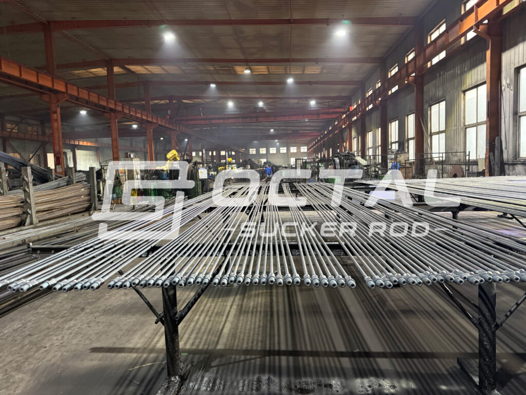
Nominal axial stress equals axial load divided by rod-body area. The following values show how diameter changes body stress under the same static load. They are calculated engineering references, not rated capacities, because an operating rod experiences cyclic load and may be limited by the connection, upset transition, wear, corrosion, bending or fatigue criterion before the nominal body reaches yield.
| Nominal diameter | Stress at 10,000 lbf | Stress at 20,000 lbf | Stress at 30,000 lbf | Stress at 40,000 lbf |
|---|---|---|---|---|
| 5/8 in. | 32.6 ksi | 65.2 ksi | 97.8 ksi | 130.4 ksi |
| 3/4 in. | 22.6 ksi | 45.3 ksi | 67.9 ksi | 90.5 ksi |
| 7/8 in. | 16.6 ksi | 33.3 ksi | 49.9 ksi | 66.5 ksi |
| 1 in. | 12.7 ksi | 25.5 ksi | 38.2 ksi | 50.9 ksi |
| 1 1/8 in. | 10.1 ksi | 20.1 ksi | 30.2 ksi | 40.2 ksi |
The table explains why a tapered rod string normally places larger or higher-strength sections nearer the surface, where the rods carry the weight and operating load of the components below. Selection must use the maximum and minimum load through the full pumping cycle, not only the polished-rod peak load or the material yield value.
The Grade DA minimums can also be converted into theoretical nominal body loads. These values only show the force associated with uniform body stress at the stated material threshold; they do not account for fatigue, connection area, manufacturing tolerance or service factors and must not be published as safe working loads.
| Nominal diameter | Theoretical load at 85 ksi body stress | Theoretical load at 115 ksi body stress | Correct interpretation |
|---|---|---|---|
| 5/8 in. | 26.1 klbf | 35.3 klbf | Nominal body calculation only |
| 3/4 in. | 37.6 klbf | 50.8 klbf | Nominal body calculation only |
| 7/8 in. | 51.1 klbf | 69.2 klbf | Nominal body calculation only |
| 1 in. | 66.8 klbf | 90.3 klbf | Nominal body calculation only |
| 1 1/8 in. | 84.5 klbf | 114.3 klbf | Nominal body calculation only |
A complete design calculates rod weight, fluid load, buoyancy, pump load and acceleration; resolves the maximum and minimum stress in every taper; checks the pin and upset sections separately; and then applies the approved fatigue method and service factor. Well depth cannot be assigned from “4130” alone because pump diameter, stroke, pumping speed, fluid density, tubing geometry and deviation can change the rod load substantially.
Manufacturing and Heat-Treatment Control
Manufacturing converts certified 4130 alloy steel into a fatigue-sensitive load-carrying component. The process must preserve heat identity while controlling forged transitions, through-section properties, straightness, surface condition and connection geometry. A heat-treatment cycle copied from a general 4130 steel data sheet does not establish a qualified sucker-rod process; section size, furnace uniformity, quench severity and required finished grade all affect the result.
| Manufacturing stage | Quantitative or process control | Required production evidence |
|---|---|---|
| Incoming bar release | AISI 4130 identity includes 0.28–0.33% C, 0.80–1.10% Cr and 0.15–0.25% Mo; the complete heat analysis must meet the ordered chemistry | Material certificate, heat map and specified full-length electromagnetic or ultrasonic examination |
| End heating and upsetting | General 4130 hot-forging references cover approximately 954–1,204°C (1,750–2,200°F); the actual shop window must be narrower and procedure-qualified | Recorded heating parameters, forging-lot identity, visual examination and specified surface-discontinuity inspection |
| Normalizing, where used | Typical 4130 normalizing reference: 871–927°C (1,600–1,700°F), followed by controlled air cooling | Furnace chart, load identity, heating time and cooling-route record |
| Quench-and-temper processing, where used | Typical 4130 austenitizing reference: 871–899°C (1,600–1,650°F); tempering is commonly developed within approximately 399–566°C (750–1,050°F) | Qualified procedure, furnace chart, quenchant identity, temperature record and processing-lot traceability |
| Straightening | Finished straightness must meet the dimensional limits of the specified API 11B edition and purchase order | Recorded straightness measurement and post-straightening surface inspection |
| Pin and shoulder finishing | Pin, shoulder and coupling dimensions must match the ordered API connection and pass the applicable working gauges | Calibrated gauge identity, calibration status and dimensional inspection record |
| Optional surface enhancement | Shot-peening coverage and Almen intensity remain procedure- and order-specific; Grade DA does not establish one universal value for every product | Approved procedure, coverage and intensity result where specified, plus lot traceability |
| Final release | Ordered body diameters normally range from 5/8 to 1 1/8 in. (15.88–28.58 mm); full-length rods are commonly 25 or 30 ft (7.62 or 9.14 m) | Final inspection report, Grade DA marking check, heat/lot reconciliation and packing list |
The forging and heat-treatment temperatures above are metallurgical process-development references for 4130 steel, not universal API acceptance limits. The manufacturer must establish the actual set points, holding times, transfer time, cooling rate, quenchant condition and tempering cycle for its equipment and rod section. Product release depends on the finished test results and documented process consistency rather than on matching a generic furnace temperature alone.
The forged upset must blend into the straight rod body without abrupt, asymmetric or visibly damaged transitions. Laps, cracks and injurious seams are critical because the upset transition combines axial stress with local bending stress. Grinding or another repair method should only follow an approved procedure that preserves the specified profile and minimum section.
The final processing route must produce the finished Grade DA properties rather than merely fall inside a nominal furnace-temperature range.
| Finished-product release item | Grade DA acceptance requirement | Verification |
|---|---|---|
| Material family | UNS G41XX0 alloy steel; AISI 4130 is UNS G41300 | Heat-linked chemical analysis |
| Minimum yield strength | 85 ksi / 586 MPa | Finished-condition tensile test |
| Tensile-strength range | 115–140 ksi / 793–965 MPa | Finished-condition tensile test |
| Minimum elongation | 10% | Recorded elongation from the specified tensile specimen |
| Minimum reduction of area | 40% | Recorded reduction-of-area result |
| API identification color | Yellow | Final marking and visual release inspection |
Final tensile testing closes the control loop. A rod that entered the furnace as certified 4130 steel cannot be released as Grade DA when its yield strength, tensile range or ductility falls outside the specified values. The tensile specimen, furnace load, heat number and finished production lot must therefore remain connected by the same traceability record.
For orders that require independent verification, Octal Sucker Rod can coordinate purchaser-appointed third-party inspection before shipment. The agreed inspection and test plan may cover heat-number traceability, material certificates, dimensional and working-gauge records, witnessed tensile testing, NDT record review, product marking and packing. Octal Steel’s third-party inspection support for steel products explains how inspection scheduling, document preparation and shipment release are coordinated for export orders.
End Geometry and Coupling Compatibility
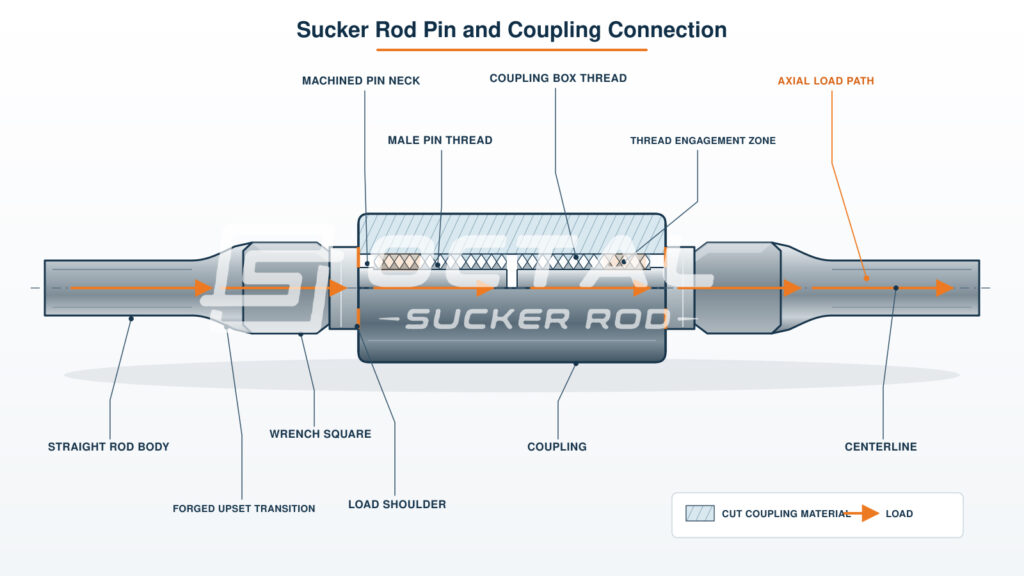
The connection transfers cyclic load from one rod to the next through two pin threads, two shoulders and a coupling. Correct thread engagement alone does not make mismatched components interchangeable. Pin designation, coupling type, outside diameter, grade, shoulder condition and the approved makeup procedure must work as one connection system.
| Connection feature | Primary function | Inspection concern |
|---|---|---|
| Pin thread | Engages the coupling and transfers axial load | Thread form, taper or lead where applicable, pitch diameter, damage and gauge acceptance |
| Shoulder | Establishes the designed makeup position and load path | Flatness, perpendicularity, surface damage and dimensional location |
| Wrench square | Allows controlled assembly and disassembly | Width, alignment, tool damage and forged-surface condition |
| Upset transition | Changes section from rod body to enlarged end | Smooth profile, sound metal flow and absence of fatigue-starting discontinuities |
| Coupling | Joins two rod pins and maintains connection alignment | Correct thread designation, coupling grade, outside diameter, wear and corrosion |
API-compatible working gauges should be identified and maintained within their calibration status. The inspection record should show the gauge identification and result rather than merely state that the thread “looks acceptable.” Field makeup must follow the connection-specific procedure. A torque value taken from another rod size, coupling type or manufacturer should not be treated as a universal setting.
Fatigue, Wear and Surface Integrity
A sucker rod normally operates below its one-time tensile capacity, yet it can fail after repeated stress cycles if a pit, lap, wrench mark, thread-root defect or rod-to-tubing contact point raises local stress. For this reason, high static strength does not replace fatigue design or surface inspection.
Diameter loss illustrates the combined effect of wear and stress. The following example assumes a nominal 7/8 in. rod under a static 20,000 lbf axial load and uniform diameter loss. Localized grooves or pits are more severe than this simplified calculation because they add a stress concentration.
| Remaining diameter | Diameter loss | Remaining body area | Area loss | Calculated body stress | Stress increase |
|---|---|---|---|---|---|
| 0.875 in. | 0% | 0.6013 in² | 0% | 33.3 ksi | 0% |
| 0.831 in. | 5% | 0.5427 in² | 9.8% | 36.9 ksi | 10.8% |
| 0.788 in. | 10% | 0.4871 in² | 19.0% | 41.1 ksi | 23.5% |
Returned-rod inspection should therefore record more than average diameter. Pit depth, groove depth, circumferential wear, bend or straightness condition, upset condition, shoulder damage and thread damage influence whether the rod can be returned to service. Retirement criteria should be agreed before inspection so that measured conditions lead to consistent dispositions.
| Damage mechanism | Evidence to collect | Engineering consequence |
|---|---|---|
| Rod-to-tubing wear | Diameter profile, wear location, deviation survey and guide spacing | Reduces area and increases bending/contact stress |
| Corrosion pitting | Pit depth, density, location and corrosion-product analysis | Raises local stress and shortens fatigue initiation time |
| Mechanical handling damage | Wrench marks, gouges, dents and bent sections | Creates stress raisers and alignment problems |
| Connection damage | Thread profile, shoulder condition, prior makeup history and gauge result | Changes load transfer and increases loosening or fatigue risk |
| Forging discontinuity | Visual, magnetic-particle or other specified examination | May initiate cracking at the upset transition |
Service Environment and Corrosion Limits
The chromium and molybdenum in 4130 steel improve hardenability and heat-treatment response, but they do not make the finished sucker rod inherently resistant to produced-fluid corrosion. Its suitability therefore depends on both the applied cyclic stress and the actual downhole environment.
| Service condition | Main engineering risk | Data required before selection |
|---|---|---|
| CO₂ and produced water | General corrosion, localized attack and corrosion-fatigue initiation | CO₂ partial pressure, water chemistry, pH, temperature and measured inhibitor residual |
| H₂S-containing production | Sulfide stress cracking and hydrogen-assisted cracking | H₂S partial pressure, pH, chloride content, finished hardness, applied stress and sour-service qualification |
| Chlorides and dissolved oxygen | Accelerated pitting and reduced inhibitor performance | Chloride concentration, dissolved oxygen, temperature and water source |
| Sand and suspended solids | Abrasive wear at rod guides and rod-to-tubing contact areas | Solids concentration, particle size, flow velocity and observed wear location |
| Deviated well sections | Additional bending stress and repeated rod-to-tubing contact | Inclination, dogleg severity, calculated contact force, tubing condition and guide spacing |
Storage preservative and transport coating protect the rod before installation; they do not establish its downhole corrosion resistance. H₂S service requires project-specific verification because chemical composition alone cannot qualify an AISI 4130 sucker rod. Finished hardness, microstructure, applied stress and the defined sour environment must be evaluated together.
Where 4130 Has an Advantage—and Where It Does Not
AISI 4130 sucker rod occupies the practical middle position between a standard carbon-steel rod and a higher-cost special-alloy rod. It is best suited when calculated cyclic loads have moved beyond the practical design range of API Grade C carbon steel, but the required strength, section size and toughness do not justify a 4330-type or proprietary high-strength alloy route.
When qualified as API Grade DA, 4130 increases the specified minimum yield strength from the Grade C baseline of 60 ksi (414 MPa) to 85 ksi (586 MPa) and the minimum tensile strength from 90 ksi (621 MPa) to 115 ksi (793 MPa). This represents a 41.7% increase in minimum yield strength and a 27.8% increase in minimum tensile strength. The result is a load-driven upgrade for moderate-to-high mechanical duty—not a maximum-strength rod or a universal solution for corrosive service.
| Alternative rod route | Relative position versus 4130 | Where 4130 is advantageous | Where the alternative may be preferable |
|---|---|---|---|
| API Grade C carbon steel | Lower API minimum yield and tensile levels | Higher Grade DA strength baseline and better heat-treatment response | Lower cost and simpler service where loads are moderate and corrosion is controlled |
| API Grade K alloy steel | Lower API minimum mechanical level with a different alloy family | Higher minimum mechanical level for load-driven selection | A qualified Grade K product may suit lower-load corrosion-oriented service |
| 4140/4142 Cr-Mo steel rod | Higher carbon content and greater strength/hardness potential | Easier balance of strength and ductility at moderate section size; potentially lower material and processing severity | Higher strength requirement may justify the higher-carbon route when toughness and hardness are controlled |
| 4330-type Ni-Cr-Mo rod | Nickel-bearing special-alloy route with strong through-section toughness potential | More economical for duties that do not need the higher-cost special-alloy route | Heavy cyclic loads or larger sections may justify the added alloy content and toughness capability |
| Corrosion-qualified proprietary rod | Chemistry, processing and limits designed around a stated environment | Suitable where load capacity is the primary driver and corrosion is controlled | Better choice where verified CO₂, H₂S or chloride performance is the governing requirement |
This comparison prevents a common specification error: selecting the highest-strength alloy without identifying the actual failure mechanism. A stronger rod may still fail from corrosion fatigue or tubing contact, while a corrosion-oriented rod may still be overloaded by an unsuitable diameter taper.
Select an AISI 4130 sucker rod by calculating the maximum and minimum stress in each rod-string section and then checking the connection, fatigue criterion, well deviation, tubing contact and produced-fluid environment. Grade DA strength can support higher calculated loads than standard-strength rods, but it cannot compensate for an undersized taper, uncontrolled corrosion, abrasive wear or an incompatible coupling.
At the order stage, Octal Sucker Rod can align the specified 4130 material, API Grade DA requirements, rod diameter, coupling configuration and inspection-document scope before production. This helps prevent a generic 4130 steel designation from being mistaken for a fully qualified sucker rod specification.
FAQ
Q: Is an AISI 4130 sucker rod automatically an API Grade DA rod?
A: No. AISI 4130 identifies a UNS G41-series alloy chemistry, which is compatible with the current Grade DA material family. The completed rod must still meet the specified minimum mechanical properties, dimensions, connection requirements, inspection, marking and traceability provisions before it can be accepted and marked as Grade DA.
Q: What strength must a Grade DA 4130 steel sucker rod reach?
A: It must meet the Grade DA minimum yield and tensile requirements shown in the finished-grade table above. These values are finished-product acceptance minimums, not allowable working stresses. The purchase specification may impose higher or narrower requirements, and the operating design must use cyclic stress, service factors and connection limits.
Q: Is 4130 steel corrosion resistant in CO₂ or H₂S wells?
A: It should not be treated as stainless steel or automatically qualified for sour service. CO₂, H₂S, chlorides, temperature, pH, water chemistry, hardness, applied stress and inhibitor performance must be evaluated together. Sour-service approval requires compliance with the applicable environmental and material qualification requirements.
Q: What information is needed to select the correct rod diameter and grade?
A: Selection requires the maximum and minimum load through the pumping cycle, pump and stroke data, fluid density, rod-string geometry, well deviation, tubing condition, CO₂/H₂S/chloride data, solids content, corrosion-control program and connection details. These inputs determine the diameter taper, finished grade, coupling, rod-guide plan and inspection interval.