
AISI 4140 sucker rod transfers cyclic tensile load between the surface pumping unit and the downhole pump while providing greater heat-treatment response than lower-carbon chromium-molybdenum steel. AISI 4140, also identified as UNS G41400, typically contains 0.38–0.43% carbon, 0.80–1.10% chromium and 0.15–0.25% molybdenum. Standard rod-body diameters extend from 5/8 to 1-1/8 in., with common nominal lengths of 25 and 30 ft. When the finished rod is ordered and qualified as API Grade DA, the current minimum mechanical requirements are 85 ksi yield strength and 115 ksi tensile strength.
Compared with lower-carbon 4130 steel, 4140 develops higher strength and hardness more readily after qualified heat treatment. This makes it useful for deep beam-pumping wells, heavily loaded upper-string sections and selected progressing-cavity-pump applications where a high strength sucker rod is required. The same metallurgy also requires tighter control of forging, heat treatment, straightening, surface condition and finished hardness. A harder rod does not automatically provide better fatigue life if the upset transition, thread root or rod body contains damaging stress concentrations.
Octal Sucker Rod matches the 4140 material route with the required API grade, rod diameter, pin configuration and coupling geometry rather than treating the alloy designation as a complete product specification. Supply packages can include full-size or slim-hole sucker rod couplings, heat-linked mechanical test reports, inspection records and manufacturing-lot traceability.
Product Data at a Glance
| Product characteristic | Standard or reference value | Engineering significance |
|---|---|---|
| Base material | AISI 4140 / UNS G41400 | Medium-carbon chromium-molybdenum alloy steel |
| Typical carbon content | 0.38–0.43% | Increases hardenability and achievable strength compared with 4130 |
| Typical chromium content | 0.80–1.10% | Improves hardenability and tempering response |
| Typical molybdenum content | 0.15–0.25% | Supports through-section response and resistance to temper softening |
| Applicable API material family | UNS G41XX0 series | Permitted material family for API Grade DA qualification |
| API Grade DA minimum yield strength | 85 ksi / 586 MPa | Minimum finished-rod acceptance value |
| API Grade DA minimum tensile strength | 115 ksi / 793 MPa | Minimum finished-rod acceptance value |
| Standard body diameters | 5/8–1-1/8 in. / 15.88–28.58 mm | Selected according to string load, suspended weight and tubing clearance |
| Common nominal lengths | 25 or 30 ft / 7.62 or 9.14 m | Nominal rod length should be distinguished from assembled length |
| Standard reference | API Spec 11B, 28th Edition with applicable addenda | Purchase order should identify the required edition |
| Coupling options | Full-size or slim-hole | Selected according to tubing ID, connection capacity and wear allowance |
| Operating load | Cyclic axial load; combined axial and torsional load where applicable | Load model must correspond to beam-pumping or PCP operation |
The alloy designation identifies the steel chemistry. It does not independently establish the finished API grade, mechanical properties, fatigue resistance, connection accuracy or suitability for a particular well environment.
Material Identity and API Grade Qualification
AISI 4140 is a raw-material designation, while API Grade DA is a finished-product classification. The two descriptions are related, but they are not interchangeable.
| Identification item | What it establishes | What it does not establish |
|---|---|---|
| AISI 4140 | Nominal alloy chemistry and material family | Finished yield strength, tensile strength or API rod grade |
| UNS G41400 | Unified material designation for 4140 steel | Compliance with sucker-rod manufacturing requirements |
| API Grade DA | Finished strength class using an allowed G41XX0 alloy route | Automatic suitability for every corrosive or sour well |
| Heat number | Traceability to the steelmaking heat and chemical analysis | Uniform finished properties without qualified heat treatment |
| Heat-treatment lot | Connection between processing records and mechanical tests | Interchangeability with rods from another lot |
| Rod marking | Manufacturer, size, grade and traceability information | Remaining condition after field service |
| Coupling identification | Coupling type, size and grade | Correct field make-up without a qualified procedure |
The finished product must also satisfy the applicable API 11B sucker rod requirements for dimensions, connections, gauging and inspection. A valid release therefore needs evidence for both material identity and finished-product performance. Listing AISI 4140 on a material certificate does not replace mechanical testing, dimensional verification, thread gauging or final rod inspection.
Chemical Composition and Heat-Treatment Response
The following ranges describe commonly specified 4140 steel properties at the raw-material level. Final acceptance should follow the material specification stated in the purchase order and the actual heat analysis shown on the material certificate.
| Element | Typical AISI 4140 range | Function in the sucker rod | Control concern |
|---|---|---|---|
| Carbon | 0.38–0.43% | Increases strength, hardness and heat-treatment response | Excessive finished hardness can reduce notch tolerance |
| Manganese | 0.75–1.00% | Supports hardenability, strength and deoxidation | Segregation must be controlled during steelmaking |
| Silicon | 0.15–0.30% | Acts as a deoxidizer and provides moderate strengthening | Must remain within the ordered chemistry range |
| Chromium | 0.80–1.10% | Improves hardenability and tempering response | Does not make the rod corrosion resistant |
| Molybdenum | 0.15–0.25% | Improves through-section response and tempering stability | Must be verified by heat analysis |
| Phosphorus | 0.035% maximum | Residual element | Excess content can reduce toughness |
| Sulfur | 0.040% maximum | Residual element | Sulfide inclusions can become fatigue-initiation sites |
| Iron | Balance | Base metal | Internal cleanliness and soundness remain important |
Higher hardenability is useful only when the manufacturing route produces consistent properties from the straight rod body through the forged upset. The heat-treatment record should identify the lot, furnace, recorded cycle, control instruments and subsequent tempering operation. Mechanical specimens must remain traceable to the same processed lot.
Generic property values for annealed or normalized 4140 bar should not be used as finished sucker-rod acceptance values. Rod properties depend on section size, heating uniformity, cooling severity, tempering practice and the location from which the mechanical specimen is taken.
Finished Mechanical Properties and Acceptance Basis
Mechanical requirements apply to the finished sucker rod rather than to the incoming alloy bar. Chemical composition establishes the material route, while tensile testing confirms whether the manufacturing and heat-treatment process produced the required grade.
| Acceptance characteristic | API Grade DA minimum or requirement | Purchase specification treatment |
|---|---|---|
| Yield strength | 85 ksi / 586 MPa minimum | State the minimum value and required test method |
| Tensile strength | 115 ksi / 793 MPa minimum | Require results linked to the treatment lot |
| Elongation | No universal value in the current Grade DA classification table | State a minimum when project qualification requires it |
| Reduction of area | No universal value in the current Grade DA classification table | Add a minimum where ductility control is required |
| Maximum hardness | No universal Grade DA limit | Specify for sour-service, hydrogen or fatigue control |
| Straightness | According to the ordered API requirements and approved drawing | Require a measured result rather than visual acceptance alone |
| Surface condition | Free from rejectable cracks, laps and injurious seams | Define inspection method and acceptance criteria |
| Pin thread | Must match the ordered connection and gauge system | Require calibrated working-gauge verification |
| Grade identification | API grade and required traceability marking | Confirm during final inspection |
The minimum yield and tensile strengths are product-release criteria, not allowable working stresses. Rod-string design must still consider mean stress, stress range, dynamic amplification, bending, corrosion, wear, connection geometry and the required safety margin.
AISI 4140 Compared with 4130
The practical advantage of 4140 does not come from carbon content alone. Its value lies in producing a controlled combination of strength, hardness and through-section consistency after qualified heat treatment.
| Comparison factor | AISI 4130 | AISI 4140 | Effect on sucker-rod selection |
|---|---|---|---|
| Typical carbon range | 0.28–0.33% | 0.38–0.43% | 4140 normally develops higher strength and hardness under comparable treatment |
| Typical chromium range | 0.80–1.10% | 0.80–1.10% | Both materials use chromium to improve hardenability |
| Typical molybdenum range | 0.15–0.25% | 0.15–0.25% | Both benefit from molybdenum during heat treatment |
| Heat-treatment response | Moderate | Higher | 4140 offers greater high-strength potential |
| Ductility margin at similar processing severity | Generally easier to retain | Requires closer hardness and tempering control | Finished tests remain more important than chemistry alone |
| Sensitivity to surface damage in a high-strength condition | Significant | Potentially greater | Forged transitions, threads and handling marks need close control |
| Corrosion resistance | Not inherently corrosion resistant | Not inherently corrosion resistant | Neither material replaces inhibition and monitoring |
| API grade outcome | Depends on finished qualification | Depends on finished qualification | The material name does not automatically establish the API grade |
In a practical 4140 vs 4130 decision, 4140 is preferable when higher hardenability and finished strength are required. However, a correctly manufactured 4130 rod may provide better service than a poorly heat-treated or surface-damaged 4140 rod.
Nickel-bearing high-strength alloys may offer greater toughness or section response under more severe loading, but they normally introduce higher alloy cost and still require environmental and connection qualification. AISI 4140 occupies a useful position between conventional lower-carbon chromium-molybdenum steel and more highly alloyed ultra-high-strength rod materials.
Rod Size and Theoretical Body Mass
The following values are calculated from a solid circular rod body using a steel density of 7,850 kg/m³. They exclude forged ends, threads, couplings, coatings and manufacturing tolerances.
| Nominal diameter | Metric diameter | Body area | Theoretical mass | Body-only mass at 25 ft | Body-only mass at 30 ft |
|---|---|---|---|---|---|
| 5/8 in. | 15.88 mm | 0.3068 in² / 197.9 mm² | 1.554 kg/m | 11.84 kg | 14.21 kg |
| 3/4 in. | 19.05 mm | 0.4418 in² / 285.0 mm² | 2.237 kg/m | 17.05 kg | 20.46 kg |
| 7/8 in. | 22.23 mm | 0.6013 in² / 387.9 mm² | 3.045 kg/m | 23.20 kg | 27.84 kg |
| 1 in. | 25.40 mm | 0.7854 in² / 506.7 mm² | 3.978 kg/m | 30.31 kg | 36.38 kg |
| 1-1/8 in. | 28.58 mm | 0.9940 in² / 641.3 mm² | 5.034 kg/m | 38.36 kg | 46.03 kg |
Increasing the body diameter reduces nominal axial stress but also increases the suspended steel weight carried by the upper string. Installing the largest diameter throughout the well therefore does not automatically produce the lowest maximum stress.
Nominal Axial-Load Reference
| Nominal diameter | Stress at 20 klbf axial load | Stress at 30 klbf axial load | Theoretical body force at 85 ksi |
|---|---|---|---|
| 5/8 in. | 65.2 ksi | 97.8 ksi | 26.1 klbf |
| 3/4 in. | 45.3 ksi | 67.9 ksi | 37.6 klbf |
| 7/8 in. | 33.3 ksi | 49.9 ksi | 51.1 klbf |
| 1 in. | 25.5 ksi | 38.2 ksi | 66.8 klbf |
| 1-1/8 in. | 20.1 ksi | 30.2 ksi | 84.5 klbf |
The theoretical force is calculated from the nominal body area and the minimum Grade DA yield strength. It is not a working-load rating. The forged transition, pin connection, thread root, corrosion loss, fatigue stress range or smallest effective section may govern before the straight body reaches nominal yield.
The final rod diameter should therefore follow the calculated load distribution rather than pump depth alone. Suspended rod weight, fluid load, polished-rod load, stroke acceleration and taper arrangement determine the primary axial demand, while tubing clearance, well deviation, corrosion exposure and retained-connection compatibility establish the practical limits of the selected string. Increasing the body diameter lowers nominal axial stress, but the added steel weight also increases the load carried by the upper rods; the lowest calculated stress may therefore come from a properly tapered string rather than a single large diameter throughout the well.
Combined Axial and Torsional Loading
Beam-pumping strings are dominated by cyclic axial loading. Progressing-cavity-pump installations can apply axial load and torque simultaneously, so an axial-only stress calculation may underestimate the actual demand on the steel sucker rod.
For a solid circular rod, preliminary checks can use axial stress, torsional shear stress and von Mises equivalent stress. Connection stress concentration, bending, tubing contact and corrosion must then be considered separately.
| Illustrative input or result | Value |
|---|---|
| Rod diameter | 7/8 in. |
| Axial load | 20,000 lbf |
| Applied torque | 300 lbf-ft / 3,600 lbf-in. |
| Calculated nominal axial stress | 33.3 ksi |
| Calculated nominal torsional shear stress | 27.4 ksi |
| Calculated von Mises equivalent stress | 57.9 ksi |
| API Grade DA minimum yield strength for comparison | 85 ksi |
This example demonstrates how torsion raises the equivalent stress even when the axial stress appears moderate. The result remains preliminary because it does not include pin-root concentration, side loading, diameter loss, corrosion pits or transient torque.
Rod-End Geometry and Coupling Compatibility
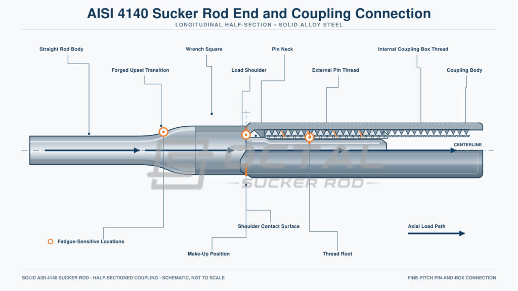
Each rod end changes from the straight body into a forged upset, wrench square, load shoulder, machined pin neck and external thread. This region carries every operating cycle while combining multiple changes in geometry.
| Connection feature | Required control | Quantified inspection scope | Objective evidence |
|---|---|---|---|
| Forged upset transition | Smooth section change, continuous metal flow and no rejectable cracks, laps or folds | 2 transitions per rod; 100% visual examination; surface NDT when specified | Visual record and applicable MPI or other surface-NDT report |
| Wrench square | Width, alignment, corner condition and position according to the approved drawing | 2 wrench squares per rod; both ends dimensionally checked | Calibrated dimensional record |
| Load shoulder | Correct position, flatness, perpendicularity and freedom from handling damage | 2 shoulders per rod; 100% visual and dimensional verification | Inspection result linked to the rod lot |
| Pin neck | Correct diameter, concentricity and machined surface condition | 2 pin necks per rod; both ends measured | Calibrated dimensional report |
| External pin thread | Correct API thread form, lead, pitch diameter and ordered connection geometry | Normally 10 TPI; 2 pins per rod; 100% working-gauge inspection | Gauge identification, calibration status and pass result |
| Coupling box thread | Connection designation and gauge system matched to the rod pin | Normally 10 TPI; 2 threaded openings per coupling | Coupling identification and calibrated gauge result |
| Make-up position | Full shoulder contact and specified circumferential displacement | Every assembled field joint; displacement value selected by rod size and grade | Approved make-up procedure and field record |
| Thread protection | Pin threads and coupling openings clean, coated where specified and protected from impact | 2 pin protectors per rod; both coupling openings protected | Final preservation and packing inspection |
The inspection coverage above distinguishes a rod-end control point from a general production sample. A standard rod has two forged transitions, two wrench squares, two load shoulders and two external pins; damage at either end can interrupt the connection load path even when the straight rod body meets its tensile requirements.
Nominal thread designation and pitch do not by themselves prove interchangeability. Replacement projects should identify the applicable API edition, connection revision, working-gauge system and coupling condition before combining rods and couplings from different production periods.
Coupling Dimensions and Tubing Clearance
| Rod size | Full-size coupling OD | Slim-hole coupling OD | Nominal coupling length |
|---|---|---|---|
| 5/8 in. | 1.500 in. / 38.1 mm | 1.252 in. / 31.8 mm | 4.000 in. / 101.6 mm |
| 3/4 in. | 1.625 in. / 41.3 mm | 1.500 in. / 38.1 mm | 4.000 in. / 101.6 mm |
| 7/8 in. | 1.811 in. / 46.0 mm | 1.626 in. / 41.3 mm | 4.000 in. / 101.6 mm |
| 1 in. | 2.189 in. / 55.6 mm | 2.000 in. / 50.8 mm | 4.000 in. / 101.6 mm |
| 1-1/8 in. | 2.375 in. / 60.3 mm | 2.258 in. / 57.4 mm | 4.500 in. / 114.3 mm |
A slim-hole coupling provides additional tubing clearance, but the smaller outside diameter should not be selected only to solve an interference problem. Connection capacity, tubing wear, make-up procedure and the specified coupling grade must also be verified.
Manufacturing and Heat-Treatment Control
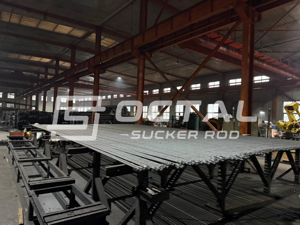
Manufacturing converts certified 4140 alloy steel into a fatigue-sensitive load-carrying component. The process must preserve heat identity while controlling forged transitions, heat-treated properties, straightness, surface condition and connection geometry.
| Manufacturing stage | Quantified control level | Main control objective | Required release evidence |
|---|---|---|---|
| Incoming steel and bar examination | Each steel heat identified; full-length NDT applied when specified by the inspection plan | Verify AISI 4140 chemistry, heat identity and bar soundness before forging | Material certificate, heat analysis, heat map and applicable NDT report |
| End heating and forging | Both ends of every rod visually examined after forging | Form the upset transition, wrench square, shoulder and pin stock without cracks, laps, folds or overheating damage | Forging record, end dimensions and applicable surface-NDT result |
| Heat treatment | Each processing lot covered by a traceable furnace record | Control heating, quenching and tempering as one qualified cycle | Furnace chart, equipment identification, lot number and calibration status |
| Mechanical and hardness testing | Required tensile specimens linked to each release lot; hardness checked at the rod ends and representative body locations under the approved ITP | Verify Grade DA strength and detect abnormal variation between the body and forged ends | Tensile-test report and hardness inspection record |
| Straightening | Full finished length of every rod checked | Meet straightness requirements without introducing tool marks or localized cold-work damage | Straightness result and post-straightening surface inspection |
| Pin, shoulder and coupling inspection | Both rod connections controlled; coupling grade, OD and thread designation verified | Confirm pin geometry, shoulder position, gauge compatibility and coupling match | Dimensional report, calibrated gauge result and coupling traceability record |
| Final release and protection | Every rod checked for surface condition, marking and thread protection before packing | Prevent damaged, mixed-grade or unidentified products from shipment | Final release record and packing list |
The numerical coverage in this table defines where control is applied; it does not convert every operation into an API-mandated inspection frequency. The applicable API edition and approved inspection and test plan remain controlling where they require stricter sampling or additional examination.
Heat-treatment acceptance should be based on finished mechanical properties and lot consistency rather than furnace temperature alone. Furnace settings cannot be transferred directly between different rod diameters, furnace designs, loading patterns or quenching systems. A recorded cycle is useful only when it remains traceable to the tensile results and finished rods released from that processing lot.
Manufacturing control should concentrate on the locations most likely to initiate fatigue failure. Forging laps, abrupt transitions, straightening marks and thread-root damage can cancel the benefit obtained from the higher strength of 4140 steel.
A material certificate identifying AISI 4140 does not by itself qualify the finished sucker rod. Product release should also include heat-treatment-lot traceability, finished tensile-test results, applicable NDT records, rod-end dimensional inspection and calibrated thread-gauge results. Rod markings, coupling identification and packing documents should remain traceable to the same released manufacturing lot.
Octal Sucker Rod can supply rods and matched couplings with a consolidated documentation package covering material identity, heat treatment, mechanical testing, connection inspection and final lot release. This allows the purchaser to verify the finished API grade instead of relying only on the nominal 4140 alloy designation.
Fatigue, Surface Condition and Handling
A continuously operating sucker rod can accumulate millions of load reversals. Static yield strength therefore represents only one part of service performance.
| Pumping rate | Cycles per day | Approximate cycles per year |
|---|---|---|
| 6 strokes/min | 8,640 | 3.15 million |
| 8 strokes/min | 11,520 | 4.20 million |
| 10 strokes/min | 14,400 | 5.26 million |
| 12 strokes/min | 17,280 | 6.31 million |
Mean load and alternating load determine the fatigue demand. A shallow scratch, corrosion pit or clamp mark can produce a local stress considerably higher than the nominal stress calculated from the original rod diameter.
| Fatigue-sensitive location | Quantified reference | Why it matters | Practical control |
|---|---|---|---|
| Forged transition | 2 transitions per rod; both ends carry every pumping cycle | Section geometry changes from the straight body to the enlarged forged end, increasing local stress sensitivity | 100% visual examination with surface NDT when required |
| Thread root | Normally 10 TPI; 2 external pins per rod | Repeated connection load acts through a machined root with local stress concentration | 100% working-gauge inspection, controlled machining and protection from impact damage |
| Load shoulder | 2 shoulders per rod | Shoulder contact establishes connection position and transfers preload into the coupling | Visual and dimensional inspection of both shoulders |
| Straightened rod body | Full finished length of 7.62 or 9.14 m for standard rods | Local tool marks or excessive straightening can introduce surface damage and residual stress | Full-length straightness measurement followed by surface inspection |
| Rod-to-tubing contact area | A 7/8 in. full-size coupling has an OD of 46.0 mm, compared with 41.3 mm for a slim-hole coupling | The 4.7 mm diameter reduction provides approximately 2.35 mm additional radial clearance when tubing ID remains unchanged | Verify tubing ID, well deviation, coupling capacity and rod-guide arrangement |
| Uniform diameter loss | A 0.50 mm radial loss on a 7/8 in. rod reduces the diameter from 22.23 to approximately 21.23 mm | The calculated body area falls by approximately 8.8%, increasing nominal axial stress by approximately 9.7% | Measure the remaining diameter and evaluate the result against the load range and used-rod criteria |
| Corrosion pit | Pit depth and tip radius control the local concentration; average diameter loss alone is insufficient | A localized pit can produce a much higher peak stress than uniform metal loss of the same average depth | Record pit location and geometry; assess together with operating stress and corrosion history |
| Clamp or tong mark | Every rod requires visual examination before installation or reuse | A sharp gouge can initiate a fatigue crack even when the remaining average diameter appears acceptable | Use protected lifting equipment and subject sharp or crack-like marks to engineering evaluation |
These values are calculation references rather than field rejection limits. Uniform metal loss can be evaluated from the remaining cross-sectional area, but a corrosion pit, thread-root defect or sharp handling mark also introduces a local stress concentration that cannot be determined from average diameter alone. Final acceptance must consider defect geometry, location, remaining section, operating-load range and the applicable used-rod inspection procedure.
Service Limits of AISI 4140 Sucker Rods
AISI 4140 obtains its strength from alloy chemistry and controlled heat treatment, not from corrosion resistance. Its chromium content improves hardenability but does not make the rod resistant to produced-water corrosion, hydrogen damage or abrasive wear.
| Operating condition | Primary concern | Required verification |
|---|---|---|
| CO₂-bearing or corrosive produced fluid | General corrosion, pitting and fatigue-crack initiation | Produced-water analysis, inhibitor program and inspection interval |
| H₂S-containing service | Hydrogen damage and sulfide stress cracking, particularly at excessive hardness | Environmental qualification, finished hardness limit and documented material approval |
| Deviated or solids-producing well | Rod-to-tubing contact, bending fatigue and abrasive diameter loss | Well-trajectory review, rod-guide design and wear monitoring |
| PCP installation | Combined axial stress, torsional stress and connection loading | Torque, axial-load, coupling-capacity and tubing-clearance calculations |
AISI 4140 sucker rod should not be selected for sour or strongly corrosive service from tensile strength alone. Finished hardness, applied stress, fluid chemistry, corrosion control and connection condition must be evaluated together.
A purchase description should identify the required API edition, finished grade, rod diameter, nominal length, pin connection, coupling type, inspection scope, documentation level and service environment. AISI 4140 can then be stated as the required material route rather than used as a substitute for the complete product specification.
FAQ
Does AISI 4140 automatically qualify as an API Grade DA sucker rod?
No. AISI 4140 belongs to the permitted G41XX0 alloy family, but the finished rod must still meet the applicable mechanical, dimensional, manufacturing, inspection and marking requirements. Material chemistry alone does not prove API Grade DA compliance.
What is the main difference between an AISI 4140 sucker rod and a 4130 rod?
AISI 4140 contains more carbon and normally develops higher strength and hardness after comparable heat treatment. This gives it greater high-strength potential, but also makes heat-treatment consistency, finished hardness and surface integrity more important.
Can an AISI 4140 sucker rod be used in an H₂S well?
The alloy designation alone is not sufficient for sour-service approval. Selection requires a documented review of H₂S exposure, fluid chemistry, temperature, finished hardness, applied stress, corrosion control and the applicable environmental qualification requirements.
What information is needed to specify an AISI 4140 sucker rod?
The specification should state the finished API grade, rod diameter, nominal length, pin connection, coupling type, tubing ID, expected axial load, torque where applicable, produced-fluid chemistry, well deviation and required inspection documentation. These inputs determine whether the requested material, rod size and connection are suitable for the operating condition.