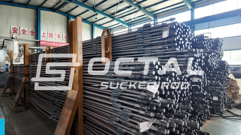
AISI 4138 sucker rod carries reciprocating axial load from the surface pumping unit through the rod string to the downhole pump. It uses modified UNS G41380 chromium-molybdenum steel, forged rod ends and a normalized-and-tempered heat-treatment route to obtain a practical balance of strength, ductility and hardenability. A commonly specified high-strength finished condition has a minimum yield strength of 115,000 psi (793 MPa), tensile strength of 140,000–155,000 psi (965–1,069 MPa), minimum elongation of 8% over an 8 in. gauge length, minimum reduction of area of 30% and maximum hardness of approximately 32 HRC.
The material occupies a useful position between standard D-family rods and more highly alloyed ultra-high-strength rods. Conventional D-family products commonly start at 85,000 psi (586 MPa) minimum yield strength and 115,000–140,000 psi (793–965 MPa) tensile strength. A heat-treated 4138M steel sucker rod can raise the minimum yield level to approximately 115,000 psi without relying on the higher nickel content commonly used in 4330M-type ultra-high-strength steel. It is therefore most useful when calculated rod loading has moved beyond the practical range of a conventional rod, but the well does not justify the additional alloy cost or toughness margin of a nickel-rich ultra-high-strength product.
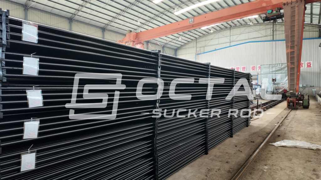
For an Octal Sucker Rod order, material grade is matched with rod diameter, length, connection revision, coupling configuration and finished mechanical properties before production is released. Standard supply can cover rod bodies from 5/8 to 1-1/8 in., nominal lengths of 25 or 30 ft, and matched full-size or slim-hole couplings. The supply file can connect the heat number and heat-treatment lot with chemical analysis, tensile results, hardness results, thread-gauge records, dimensional inspection and final packing identification. This keeps the purchasing decision tied to measurable finished-product performance rather than to the “4138” name alone.
Product Data at a Glance
| Specification item | Reference supply range or requirement |
|---|---|
| Product | High-strength steel sucker rod |
| Material route | Modified AISI 4138 / UNS G41380 chromium-molybdenum steel |
| Primary product standard | API Spec 11B, applicable edition and addenda stated in the purchase order |
| Current reference edition | API Spec 11B, 28th Edition with Addendum 1 |
| Typical heat treatment | Normalizing and tempering |
| Reference minimum yield strength | 115,000 psi / 793 MPa |
| Reference tensile-strength range | 140,000–155,000 psi / 965–1,069 MPa |
| Reference minimum elongation | 8% over an 8 in. gauge length |
| Reference minimum reduction of area | 30% |
| Reference maximum hardness | 32 HRC |
| Standard rod-body sizes | 5/8, 3/4, 7/8, 1 and 1-1/8 in. |
| Standard nominal lengths | 25 ft / 7.62 m and 30 ft / 9.14 m |
| Rod-end construction | Forged upset, wrench square, load shoulder and external pin thread |
| Coupling options | Full-size or slim-hole; coupling material and treatment selected for the load and wear condition |
| Principal application | Deep wells, heavy fluid loads, high axial loading and selected PCP installations |
| Environmental limitation | Not automatically qualified for active corrosion or sour service |
| Required release basis | Purchase order, applicable API edition, approved product specification and inspection plan |
The values above form a practical product-page reference. They must not replace the ordered manufacturing specification. AISI 4138 identifies a steel family; it does not, by itself, establish the finished rod grade, heat treatment, mechanical-property limits or sour-service qualification.
Material Identity and Finished-Grade Qualification
Several related names appear in the sucker-rod market, but they do not describe the same requirement.
| Designation | What it controls | What it does not prove |
|---|---|---|
| AISI 4138 | General chromium-molybdenum steel chemistry family | Finished rod strength, API compliance or service suitability |
| UNS G41380 | Standardized material identity for the steel family | Exact modified chemistry used by every manufacturer |
| 4138M | Manufacturer- or project-modified 4138 chemistry | A universal mechanical-property range |
| High-strength or HA-type class | Finished strength and ductility targets under an approved product specification | Automatic corrosion or H₂S resistance |
| API 11B sucker rod | Product dimensions, connections, material classes, testing, gauging, marking and related requirements | A single universal material chemistry for every grade |
The purchase order should therefore identify both the material route and the finished-product acceptance criteria. Ordering only “AISI 4138” leaves the heat-treatment condition, mechanical grade, connection revision and inspection level undefined.
Chemical Composition and Metallurgical Function
A modified 4138 chemistry normally contains more carbon than conventional 4130 steel while retaining chromium and molybdenum additions. This increases hardenability and makes it possible to establish a stronger finished condition after normalizing and tempering. The same carbon increase also makes control of forging temperature, cooling rate and tempering consistency more important.
The following range is a practical 4138M procurement reference. The approved mill specification and heat analysis remain the governing documents.
| Element | Reference content, wt.% | Main metallurgical purpose |
|---|---|---|
| Carbon, C | 0.38–0.43 | Raises achievable strength and hardness; excessive carbon can reduce weldability and toughness |
| Manganese, Mn | 1.00–1.40 | Supports hardenability and deoxidation |
| Silicon, Si | 0.15–0.40 | Deoxidizer and moderate solid-solution strengthening element |
| Chromium, Cr | 0.50–1.00 | Improves hardenability and supports strength retention after tempering |
| Molybdenum, Mo | 0.24–0.50 | Limits temper embrittlement and improves through-section heat-treatment response |
| Nickel, Ni | 0.30 maximum | Residual or limited addition; substantially lower than common 4330M routes |
| Vanadium, V | 0.04–0.11 where specified | Supports grain refinement and precipitation strengthening |
| Niobium, Nb | 0.05 maximum where specified | May support grain-size control in a modified chemistry |
| Phosphorus, P | 0.025–0.030 maximum | Restricted because excessive phosphorus reduces toughness |
| Sulfur, S | 0.025–0.035 maximum | Restricted to control inclusions and transverse ductility |
| Copper, Cu | 0.25–0.35 maximum | Normally controlled as a residual element |
Not every 4138M producer uses an identical manganese, chromium, molybdenum or microalloy range. A heat can comply with a supplier’s modified G41380 specification without matching every value in another supplier’s data sheet. Chemical acceptance should consequently be based on one approved specification, not a mixture of favorable limits taken from several sources.
Chromium and molybdenum improve heat-treatment response; they do not convert the material into stainless steel. Active CO₂ corrosion, H₂S-assisted cracking, chloride attack and oxygen corrosion must still be evaluated separately.
Finished Mechanical Properties
The finished mechanical properties must be tested after the production heat-treatment cycle. A raw 4138 steel bar certificate proves chemical identity but does not prove that the completed sucker rod has reached its ordered strength and ductility.
| Mechanical property | Common high-strength 4138M benchmark | Acceptance significance |
|---|---|---|
| Yield strength, 0.2% offset | 115,000 psi / 793 MPa minimum | Establishes the onset of permanent deformation in the qualified finished condition |
| Ultimate tensile strength | 140,000–155,000 psi / 965–1,069 MPa | Defines the finished strength band; excessive strength may reduce ductility |
| Elongation over 8 in. | 8% minimum | Confirms that strength has not been obtained at the expense of excessive brittleness |
| Reduction of area | 30% minimum | Indicates local ductility at fracture |
| Hardness | 32 HRC maximum reference | Helps control an excessively hard condition and supports environmental assessment |
| Impact energy | Project-specific | Test temperature, specimen orientation and minimum energy must be stated if required |
| Fatigue performance | Product- and process-specific | Cannot be inferred from tensile strength alone |
Some publicly available 4138M programs use higher ductility requirements, including 10% minimum elongation and 40% minimum reduction of area. Those values are valid only when they belong to the ordered finished-grade specification. A purchase document should select one complete property set rather than combining the lowest required hardness with the highest advertised ductility from different products.
A tensile report should identify the material heat, treatment lot, specimen location, specimen dimensions, yield method, tensile result, elongation and reduction of area. The reported results must remain traceable to the delivered rods.
Where the 4138M Advantage Actually Lies
The genuine advantage of 4138M is not that it is automatically the strongest available sucker-rod steel. Its value lies in reaching a high-strength finished condition with a relatively economical chromium-molybdenum chemistry.
| Rod or material route | Minimum yield strength | Typical tensile range | Practical position | Main limitation |
|---|---|---|---|---|
| Standard C or K class | 60 ksi / 414 MPa | 90–115 ksi / 621–793 MPa | Light-to-moderate loading | Limited margin as rod-string stress increases |
| Conventional D-family / 4130-type route | 85 ksi / 586 MPa | 115–140 ksi / 793–965 MPa | Moderate-to-high beam-pumping loads | May become restrictive in deeper or heavier strings |
| 4138M high-strength route | 115 ksi / 793 MPa | 140–155 ksi / 965–1,069 MPa | Heavy axial loads without a nickel-rich UHS chemistry | Requires controlled heat treatment; not inherently corrosion resistant |
| 4330M-type UHS route | 115 ksi / 793 MPa or project-specific | Often 140–155 ksi / 965–1,069 MPa | Very high loads where greater toughness and nickel-alloy response are justified | Higher alloy content and cost |
| Grade KD sucker rod for corrosion-oriented service | Specification-specific | Specification-specific | Wells where environmental resistance governs selection | May not provide the best load/cost balance for noncorrosive service |
The tensile ranges of 4138M and 4330M products can overlap. The reason for selecting a 4330M route is therefore not always a higher published tensile number. Its nickel-chromium-molybdenum chemistry may provide a different toughness and heat-treatment response for severe loading.
The AISI 4138 sucker rod is most defensible when calculated loading exceeds the practical range of a conventional D-family rod, but the operating envelope does not require the additional alloy content or special performance margin of a 4330M ultra-high-strength rod.
Higher strength is not a substitute for a corrosion-control program, rod guides, correct coupling clearance or a dynamic rod-string analysis.
Rod-Body Size and Pulling-Force Reference
Rod diameter affects both stress and rod-string weight. Axial stress varies inversely with cross-sectional area, so a small change in diameter produces a meaningful change in nominal body stress.
The table separates the theoretical rod-body force at the minimum yield strength from a published pulling-force screen based on the smallest load-carrying section. Neither value is an allowable operating load.
| Nominal rod size | Metric body OD | Nominal body area | Body force at 115 ksi | Reference pull at 90% of minimum yield, smallest section |
|---|---|---|---|---|
| 5/8 in. | 15.88 mm | 0.307 in² | 35.3 klbf / 157 kN | 30.3 klbf / 13.8 t |
| 3/4 in. | 19.05 mm | 0.442 in² | 50.8 klbf / 226 kN | 43.7 klbf / 19.9 t |
| 7/8 in. | 22.23 mm | 0.601 in² | 69.2 klbf / 308 kN | 59.9 klbf / 27.2 t |
| 1 in. | 25.40 mm | 0.785 in² | 90.3 klbf / 402 kN | 78.3 klbf / 35.6 t |
| 1-1/8 in. | 28.58 mm | 0.994 in² | 114.3 klbf / 508 kN | 99.1 klbf / 45.1 t |
The body-force column is calculated from nominal circular area multiplied by 115 ksi. The pulling-force column is a screening reference for a like-new rod based on 90% of minimum yield at the smallest section. It does not include fatigue, corrosion loss, connection condition, bending, dynamic acceleration or uncertainty in used equipment.
A working string must be checked with calculated maximum and minimum loads throughout the pumping cycle. The rod with the smallest diameter is not always the only critical location: upset transitions, connections, deviated intervals and worn sections can control the result.
Beam-Pumping and PCP Stress Checks
Beam-pumping rods primarily carry cyclic axial load. PCP strings can carry significant axial load and continuous torque at the same time. Applying an axial-only calculation to a PCP installation can materially understate the effective stress.
| Calculation item | Engineering expression | Required input | Use |
|---|---|---|---|
| Rod-body area | A = πd²/4 | Actual or minimum body diameter | Converts load to nominal axial stress |
| Axial stress | σ = F/A | Axial load and body area | Beam-pumping and PCP load screen |
| Maximum torsional stress | τ = 16T/(πd³) | Applied torque and body diameter | PCP torsional assessment |
| Effective PCP stress | σe = √(σ² + 3τ²) | Axial and torsional stress | Combined von Mises stress screen |
| Stress range | Δσ = σmax − σmin | Maximum and minimum cycle stress | Fatigue assessment |
| Mean stress | σm = (σmax + σmin)/2 | Maximum and minimum cycle stress | Modified Goodman assessment |
| Fatigue acceptance | Approved modified Goodman method | Stress cycle, UTS, service factor and grade data | Compares the operating cycle with the selected fatigue envelope |
Illustrative Stress Screens
| Example | Input data | Calculated result | Engineering meaning |
|---|---|---|---|
| 7/8 in. beam-pumping rod | Fmax = 50,000 lbf; Fmin = 10,000 lbf; area = 0.601 in² | σmax = 83.2 ksi; σmin = 16.6 ksi; range = 66.6 ksi; mean = 49.9 ksi | Below yield does not automatically mean acceptable fatigue life; the full cycle still requires a Goodman check |
| 1 in. PCP rod | Axial load = 60,000 lbf; torque = 1,000 lbf·ft | Axial stress = 76.4 ksi; torsional stress = 61.1 ksi; effective stress = 130.5 ksi | Torque raises the combined stress well above the axial stress considered alone |
These examples illustrate calculation logic only. A final design must include rod-string weight in fluid, pump load, acceleration, stroke rate, fluid level, tubing friction, well deviation, contact force, corrosion condition and the minimum effective section of the selected product.
Rod-End Geometry and Coupling Compatibility
Every pumping cycle transfers load through the straight body, forged upset transition, wrench square, shoulder, pin thread and coupling. The rod end is therefore a load-carrying system rather than a set of independent dimensions.
The upset must merge gradually into the straight body. Abrupt section changes, forging laps, injurious seams, eccentric metal flow or local straightening damage can create a fatigue initiation point even when the body tensile test passes.
Rod-End and Coupling Dimensions
| Rod size | Rod-body OD | Nominal pin designation | Pin shoulder OD | Wrench-square width | Full-size coupling OD | Slim-hole coupling OD |
|---|---|---|---|---|---|---|
| 5/8 in. | 15.88 mm | 15/16 in. | 1.250 in. / 31.75 mm | 0.875 in. / 22.2 mm | 1.500 in. / 38.1 mm | 1.250 in. / 31.8 mm |
| 3/4 in. | 19.05 mm | 1-1/16 in. | 1.500 in. / 38.10 mm | 1.000 in. / 25.4 mm | 1.625 in. / 41.3 mm | 1.500 in. / 38.1 mm |
| 7/8 in. | 22.23 mm | 1-3/16 in. | 1.625 in. / 41.28 mm | 1.000 in. / 25.4 mm | 1.812 in. / 46.0 mm | 1.625 in. / 41.3 mm |
| 1 in. | 25.40 mm | 1-3/8 in. | 2.000 in. / 50.80 mm | 1.313 in. / 33.3 mm | 2.187 in. / 55.6 mm | 2.000 in. / 50.8 mm |
| 1-1/8 in. | 28.58 mm | 1-9/16 in. | 2.250 in. / 57.15 mm | 1.500 in. / 38.1 mm | 2.375 in. / 60.3 mm | Project-specific |
These dimensions are procurement references. Standard sucker-rod pin connections commonly use 10 threads per inch, but final thread form, pitch diameter, taper, lead, shoulder location and gauge acceptance must follow the applicable API edition and approved product drawing.
A slim-hole coupling increases tubing clearance, but its smaller outside diameter changes the connection envelope. It should be selected only after checking coupling strength, rod loading, tubing inside diameter, wear allowance and expected rod-to-tubing contact. High-load PCP service generally requires a coupling specifically qualified for the combined axial and torsional condition.
Minimum Connection-Control Requirements
Connection acceptance should combine dimensional values with functional inspection. Nominal dimensions help identify the correct component, while calibrated gauges and approved make-up procedures determine whether the connection is acceptable.
| Connection feature | Required control | Numerical reference or acceptance note | Minimum objective evidence |
|---|---|---|---|
| Upset transition | Smooth section change, sound metal flow and no rejectable cracks, laps or injurious seams | Recommended project control: 100% visual examination of both forged ends. Apply 100% surface NDT when required by the ordered grade or inspection plan. No rejectable crack or forging lap is permitted. | Visual inspection record and specified magnetic-particle or other surface-NDT report |
| Pin thread | Correct thread form, pitch diameter, lead and taper where applicable | Standard sucker-rod connections commonly use 10 threads per inch, equivalent to a 0.100 in. / 2.54 mm pitch. Nominal pin designations range from 15/16 to 1-9/16 in., depending on rod size. | Working-gauge identification, calibration status and recorded acceptance result |
| Load shoulder | Correct diameter, location, flatness and perpendicularity | Reference shoulder ODs are 1.250, 1.500, 1.625, 2.000 and 2.250 in. for rod sizes from 5/8 to 1-1/8 in. respectively. Final tolerances must follow the applicable API drawing. | Dimensional report and confirmation of complete shoulder seating after controlled make-up |
| Wrench square | Correct width, alignment and absence of damaging tool marks | Reference widths are 0.875, 1.000, 1.000, 1.313 and 1.500 in. for the five standard rod sizes. Width tolerance and square length remain drawing-specific. | Calibrated dimensional measurement and visual inspection record |
| Coupling | Correct thread designation, material class, OD and internal condition | Typical full-size coupling ODs are 1.500–2.375 in.; common slim-hole ODs range from 1.250–2.000 in. Coupling OD must match the rod size and tubing-clearance calculation. | Coupling marking, dimensional result, thread-gauge result and inspection record |
| Full-size or slim-hole selection | Adequate tubing clearance without unacceptable reduction in connection capacity | Calculate radial clearance as (minimum tubing ID − maximum coupling OD) ÷ 2. Use minimum tubing/drift ID and maximum coupling OD, not nominal tubing size. No universal minimum clearance applies to every well. | Tubing data sheet, drift ID, coupling drawing and rod-string clearance review |
| Field make-up | Correct cleaning, approved lubricant, shoulder contact and controlled make-up | At 10 TPI, one full thread revolution represents 0.100 in. / 2.54 mm of theoretical axial advance before shoulder contact. Final circumferential displacement and torque are connection-specific. | Approved make-up chart, lubricant record and field make-up control record |
| Working gauges | Gauges must match the connection revision and remain within calibration | Record the gauge ID and calibration due date. Do not assume a generic 12-month interval unless it is defined by the quality system or inspection plan. | Gauge register, calibration certificate and inspection result |
| Replacement components | Match nominal size, API edition, connection revision and gauge system | Verify all five standard sizes from 5/8 to 1-1/8 in. API Spec 11B 28th Edition Addendum 1 became effective for the API Monogram Program on April 1, 2026; legacy and current components should not be mixed by nominal size alone. | Existing component identification, drawing-revision review and new-component gauge verification |
Tubing-Clearance Calculation Example
The following example illustrates why nominal rod size alone is insufficient when selecting a coupling.
| Calculation item | Example value |
|---|---|
| Rod size | 7/8 in. |
| Full-size coupling OD | 1.812 in. / 46.02 mm |
| Example minimum tubing ID | 1.995 in. / 50.67 mm |
| Diametral clearance | 0.183 in. / 4.65 mm |
| Radial clearance | 0.0915 in. / 2.32 mm |
This is only a calculation example. The actual tubing drift diameter, scale, paraffin, rod guides, well deviation and coupling wear must be considered before the clearance is approved. A slim-hole coupling can increase clearance, but its load capacity and wear behavior must still satisfy the rod-string design.
A torque value copied from another rod diameter, coupling type or manufacturer should not be treated as a universal make-up setting. At 10 TPI, thread pitch describes axial movement during free rotation; it does not establish the required preload after the coupling reaches the rod shoulder. Final make-up should follow the approved circumferential-displacement or connection-specific procedure.
Manufacturing and Heat-Treatment Control
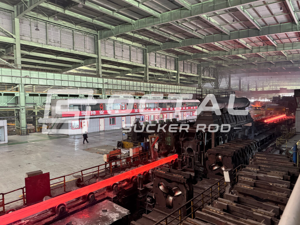
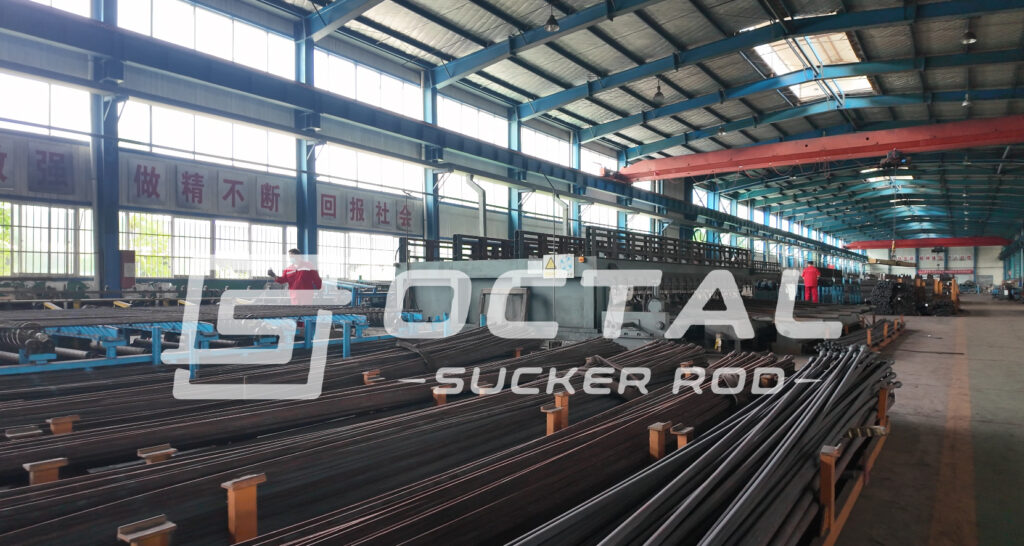
Manufacturing converts certified 4138M steel into a cyclic load-carrying component. Each production stage must preserve material traceability while controlling forged-end geometry, heat-treatment consistency, surface condition and connection accuracy.
| Manufacturing stage | Controlled characteristic | Numerical reference or minimum control | Minimum release evidence |
|---|---|---|---|
| Incoming steel release | Heat identity, chemistry, body size and initial condition | Verify at least one chemical analysis for every heat number. Reference 4138M chemistry includes 0.38–0.43% C, 0.50–1.00% Cr, 0.24–0.50% Mo and 0.30% maximum Ni; the approved material specification remains controlling. | Material certificate, heat number and heat-to-production-lot map |
| Bar examination | Surface and internal discontinuities | For a controlled high-strength program, specify 100% electromagnetic and/or ultrasonic examination of the incoming bar. Acceptance sensitivity and reference standards must be stated in the inspection plan. | NDT procedure, equipment calibration record and heat/lot-linked examination report |
| End heating and forging | Metal flow, upset size, alignment and transition profile | Local end-forging temperature is commonly around 1,200°C / 2,192°F as a manufacturing reference. The actual temperature window, heating time and die sequence must follow the qualified procedure. Conduct 100% visual examination of both forged ends. | Recorded process parameters, first-piece dimensional report and surface inspection record |
| Full-length normalizing | Uniform austenitizing and transformation through the rod section | Treat the full rod length and retain one furnace chart for each heat-treatment lot. Furnace set point, residence time and cooling rate are manufacturer-specific rather than universal API acceptance values. | Qualified procedure, furnace chart, thermocouple reference and lot identification |
| Tempering | Final hardness, ductility and strength consistency | Tempering must produce the ordered finished properties without exceeding the reference 32 HRC maximum hardness. Acceptance is based on the finished rod, not the recorded furnace temperature alone. | Furnace chart, hardness results and heat-treatment-lot record |
| Straightening | Alignment without local deformation or injurious tool marks | Verify the complete length of standard 25 ft / 7.62 m and 30 ft / 9.14 m rods. Numerical straightness tolerance must follow the applicable API edition and approved product drawing. | Recorded straightness measurement and post-straightening surface inspection |
| Optional shot peening | Controlled treatment of the specified rod-body surface | When ordered, the qualified procedure may specify at least 100% surface coverage. Almen intensity, media size and treatment area must be recorded rather than inferred from visual appearance. | Shot-peening procedure, coverage and intensity record, equipment check and lot traceability |
| Pin and shoulder machining | Thread form, pitch, concentricity, shoulder location and finish | Standard sucker-rod connections commonly use 10 TPI, equivalent to a 0.100 in. / 2.54 mm pitch. Nominal pin sizes range from 15/16 to 1-9/16 in. for standard rod-body diameters. | Dimensional report, working-gauge ID, calibration status and recorded gauge result |
| Final mechanical testing | Finished yield strength, tensile strength and ductility | Reference high-strength targets: 115 ksi / 793 MPa minimum yield, 140–155 ksi / 965–1,069 MPa tensile, 8% minimum elongation, 30% minimum reduction of area and 32 HRC maximum hardness. | Heat- or treatment-lot-linked tensile and hardness test report |
| Final inspection and traceability | Length, body diameter, surface, marking, connection protection and document completeness | Apply 100% final visual and marking inspection. Each delivered rod should be traceable to its material heat and treatment lot. Both threaded ends must be clean and protected before packing. | Final inspection report, marking list, thread-protection check, packing list and document index |
The approximate forging temperature and shot-peening coverage are process references, not universal API limits. Contract acceptance should remain tied to the approved manufacturing procedure and the measured finished-product results.
Fatigue, Surface Condition and Handling
A sucker rod completes approximately one primary tensile-load cycle during each pumping stroke. At 8 strokes per minute, this equals about 11,520 cycles per day or 4.20 million cycles per year before accounting for shutdowns. Small surface defects can therefore experience millions of repeated stress applications.
| Fatigue factor | Quantitative reference | Why it matters | Required control |
|---|---|---|---|
| Operating cycle count | 6 spm: 8,640 cycles/day and 3.15 million/year; 8 spm: 11,520/day and 4.20 million/year; 10 spm: 14,400/day and 5.26 million/year | Fatigue exposure accumulates even when every individual load cycle remains below yield strength | Use operating stroke rate, runtime and load history in the fatigue assessment |
| Surface seams or laps | Recommended control: 100% visual examination of the finished rod surface; electromagnetic or other NDT coverage as defined by the ordered inspection plan | A small longitudinal discontinuity can behave as a fatigue initiator under millions of cycles | Reject cracks, injurious laps and seams according to the governing specification |
| Forged transition profile | Inspect both upset transitions on every rod visually; apply surface NDT to 100% of the forged ends when required by the product program or ITP | The transition combines a change in section with repeated axial and bending stress | Control the forging profile, metal flow and surface condition together |
| Thread-root condition | Standard connection reference: 10 TPI, with a 0.100 in. / 2.54 mm pitch | The thread root carries repeated connection load at a local stress concentration | Use controlled machining or rolling, calibrated working gauges and protected handling |
| Shoulder damage | Reference shoulder ODs range from 1.250 to 2.250 in. across standard rod sizes | Uneven shoulder seating changes the intended load path and can overload part of the connection | Inspect shoulder flatness, surface condition and complete seating under the approved make-up procedure |
| Corrosion pits | Illustration: 0.5 mm uniform radial metal loss on a nominal 7/8 in. / 22.23 mm rod reduces the remaining cross-sectional area by approximately 8.8% and raises nominal axial stress by approximately 9.7% | A localized pit can create a greater stress increase than uniform metal loss because it also introduces a notch effect | Monitor corrosion rate and pit morphology; apply project-specific rejection criteria |
| Rod-to-tubing wear | Illustration: reducing a 7/8 in. rod diameter by 0.010 in. increases nominal axial stress by approximately 2.3% at the same load | Contact wear reduces load-carrying area while deviation adds cyclic bending stress | Use deviation analysis, rod-guide design and measured remaining diameter |
| Handling dents and clamp marks | Apply 100% visual inspection after transport and before running. Any sharp dent, gouge or measurable metal loss should trigger additional examination | Handling damage can create a fatigue origin before the rod enters service | Use protected racks, suitable lifting slings and approved handling tools |
| Used-rod mixing | Inspect and identify 100% of reused rods and connections under the applicable used-rod program | Mixed rods may have different grades, heat treatments, connection revisions and fatigue histories | Segregate by grade, diameter and connection; document visual, dimensional and NDT acceptance |
The 0.5 mm corrosion-loss and 0.010 in. wear examples illustrate how section loss increases nominal stress; they are not universal rejection limits. Final acceptance shall be based on the measured remaining section, actual maximum and minimum operating loads, and the applicable API or owner-approved used-rod inspection procedure.
Service Environment and Selection Limits
4138 chromium-molybdenum steel improves hardenability and finished strength. It does not provide universal resistance to produced-fluid corrosion.
| Well condition | Data required before selection | Selection implication |
|---|---|---|
| Noncorrosive or effectively inhibited production | Water analysis, temperature and operating history | Best-fit environment for a conventional high-strength 4138M rod |
| Active CO₂ corrosion | CO₂ partial pressure, pH, temperature, chloride level, water cut and inhibitor residual | Requires a verified corrosion-control program; material strength alone is insufficient |
| H₂S-containing production | H₂S partial pressure, pH, chloride level, hardness, applied stress and governing sour-service criteria | No automatic sour-service qualification from the 4138 name |
| Deviated well | Inclination survey, dogleg severity, contact-force model, tubing condition and guide spacing | Bending fatigue and contact wear may govern before tensile strength |
| Sand-producing well | Solids concentration, particle size, velocity and contact location | Abrasive wear may control rod, guide, coupling and tubing life |
| PCP service | Axial load, torque, speed, tubing clearance and coupling configuration | Requires combined-stress and connection assessment |
| Previous rod failures | Fracture location, metallography, corrosion morphology and operating history | Helps separate overload, corrosion fatigue, connection failure and wear |
For active H₂S exposure, the applicable sour-service standard, finished hardness, stress level and product qualification must be reviewed together. Lower hardness alone does not prove suitability, and a high-strength rod should not be approved solely because its chemistry contains chromium and molybdenum.
AISI 4138 sucker rod is best suited to deep or heavily loaded beam-pumping strings and selected PCP installations where the calculated stress exceeds the practical range of conventional D-family rods. Corrosive, sour or severely deviated wells require separate environmental, fatigue and connection qualification rather than selection by material strength alone.
Within this operating window, Octal Sucker Rod converts the available well data into a controlled product specification, aligning the 4138M finished grade with rod diameter, taper arrangement, full-size or slim-hole coupling, applicable API 11B connection revision and required inspection documents before production release. This approach selects the rod for the actual operating load and service environment instead of simply specifying the highest available strength.
FAQ
Q: Does AISI 4138 automatically qualify a rod as an API high-strength grade?
A: No. AISI 4138 or UNS G41380 identifies the steel family. The finished grade must still be established through the applicable API 11B requirements, approved manufacturer specification, heat-treatment condition and mechanical-test results.
Q: What is the main difference between a 4138 and a 4130 steel sucker rod?
A: Modified 4138 normally has a higher carbon range and can achieve a stronger normalized-and-tempered condition. A common 4138M high-strength benchmark starts at 115 ksi minimum yield strength, while many 4130 D-family products start at approximately 85 ksi. Actual comparison must use the finished-product reports rather than the material names alone.
Q: When is a 4138M rod more practical than a 4330M ultra-high-strength rod?
A: It is most practical when the modeled load exceeds the useful range of a conventional rod but does not require the additional nickel-alloy content or toughness margin of the 4330M route. The two products may have overlapping tensile-strength ranges, so the decision should consider toughness, fatigue demand, environment and total supply cost.
Q: Can API sucker rods made from 4138M be used in corrosive or sour wells?
A: Not automatically. CO₂, H₂S, chlorides, temperature, pH, inhibitor residual, finished hardness and applied stress must be evaluated. A corrosion-control plan or specially qualified material may be required before the rod is approved.