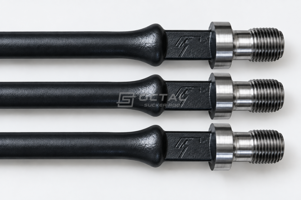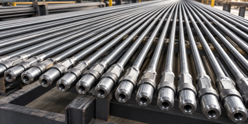
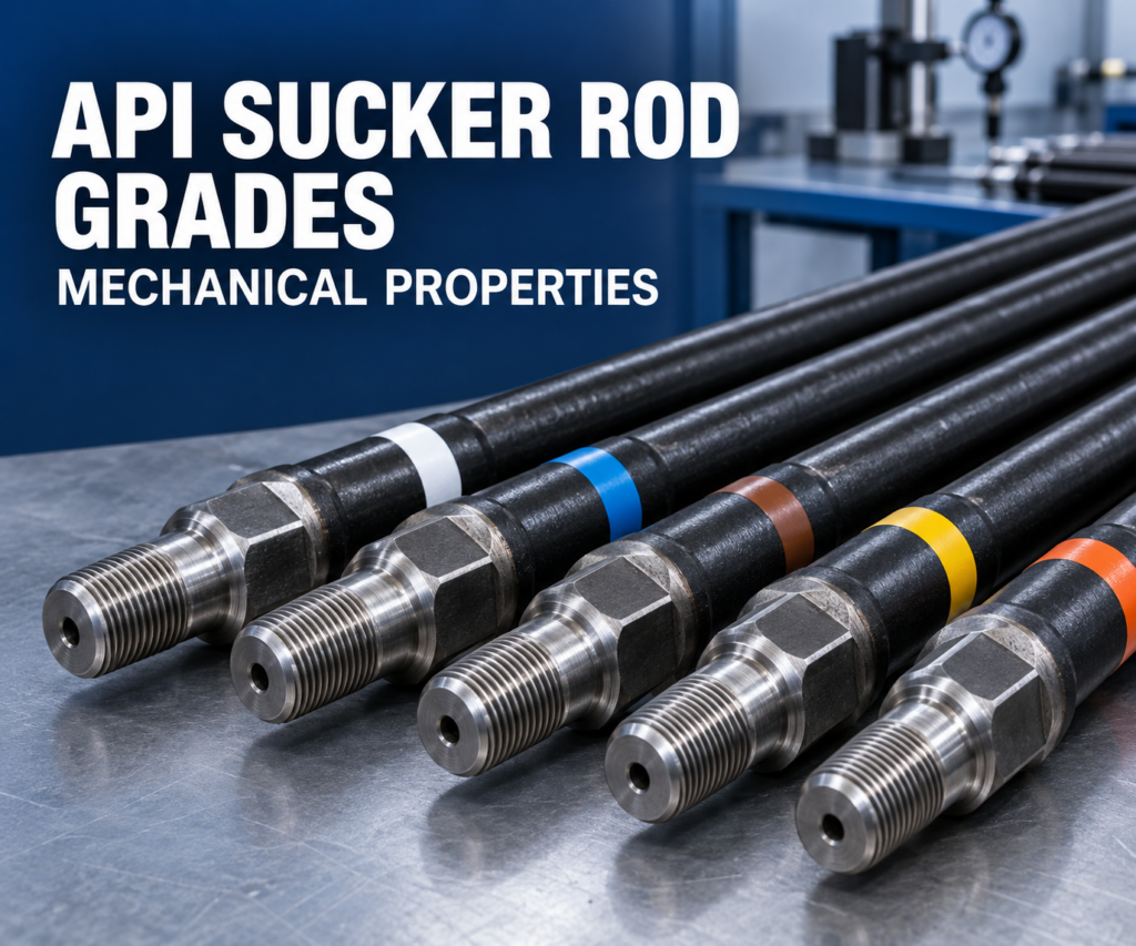
API sucker rods transfer reciprocating load from the surface pumping unit to the downhole pump through a connected rod string. Each pumping cycle changes the tensile load in the rod body, forged upset and threaded connection, so grade selection must account for yield strength, tensile strength, fatigue stress, corrosion exposure and the remaining cross-sectional area of every rod section.
API Specification 11B classifies a steel sucker rod by its material family and minimum mechanical properties. Grade C and Grade K share the standard-strength mechanical range, while the Grade D family provides a higher tensile range for more heavily loaded strings. Grade K differs from Grade C mainly through its alloy system and corrosion-oriented service position rather than through higher nominal strength.
The grade marked on the rod therefore answers only part of the selection question. A complete sucker rod design must also establish maximum and minimum cyclic stress, well deviation, fluid condition, rod diameter, connection condition and the required service factor.
How API Grade Designations Are Applied
Current API terminology identifies several material variants within the traditional Grade D category. Older technical literature and many commercial specifications still use “Grade D” as a general name, while current product documents may identify the material more precisely as DC, DA or DS.
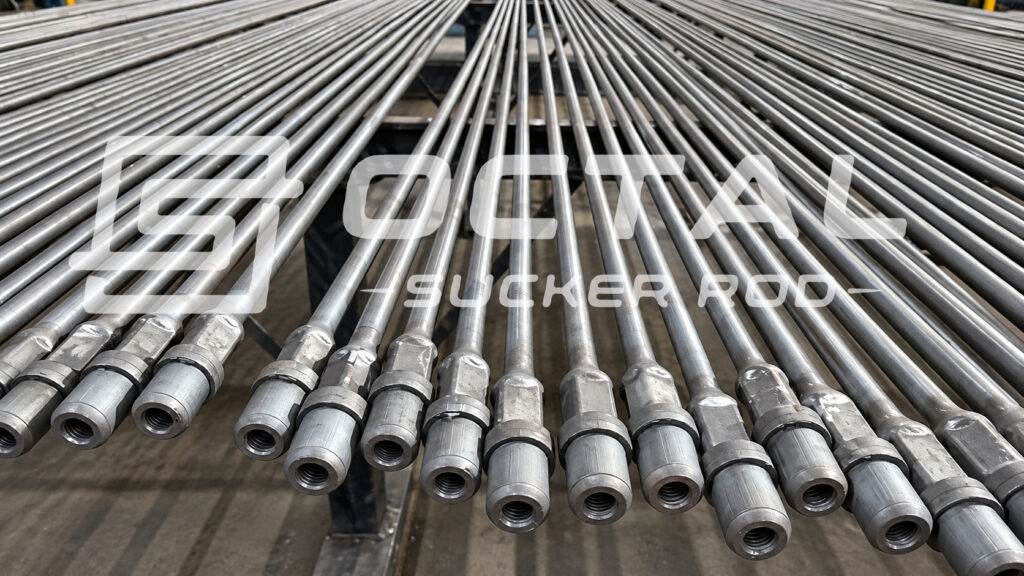
| API grade designation | Material classification | Minimum yield strength | Tensile-strength range | Minimum elongation over 8 in. | Minimum reduction of area | Identification color |
|---|---|---|---|---|---|---|
| C | Carbon steel | 60 ksi / 414 MPa | 90–115 ksi / 621–793 MPa | 13% | 40% | White |
| K | Alloy steel | 60 ksi / 414 MPa | 90–115 ksi / 621–793 MPa | 13% | 40% | Blue |
| DC | Carbon-steel Grade D family | 85 ksi / 586 MPa | 115–140 ksi / 793–965 MPa | 10% | 40% | Brown |
| DA | Alloy-steel Grade D family | 85 ksi / 586 MPa minimum API reference | 115–140 ksi / 793–965 MPa | 10% | 40% minimum | Yellow |
| DS | Special-alloy Grade D family | 85 ksi / 586 MPa minimum API reference | 115–140 ksi / 793–965 MPa | 10% | 40% minimum | Orange |
The values in this table describe the basic API mechanical envelope. A manufacturer may specify higher yield strength, greater reduction of area or a narrower tensile range for a particular product series. Those enhanced values should be treated as manufacturer-specific requirements and verified against the product datasheet and inspection certificate.
The color band provides rapid grade identification at the wellsite, but it does not replace permanent product marking or material traceability. Used rods may have faded paint, mixed couplings or replacement components, so grade verification should rely on the rod marking and supporting records.
What the Mechanical Properties Mean in Service
Yield strength, tensile strength, elongation and reduction of area describe different parts of rod behavior. Selecting a rod from tensile strength alone can conceal insufficient ductility, fatigue damage or loss of section caused by wear.
| Mechanical property | What it measures | Engineering significance |
|---|---|---|
| Yield strength | Stress at which permanent plastic deformation begins, normally evaluated using the specified offset method | Establishes the lower boundary for overload and pulling calculations |
| Ultimate tensile strength | Maximum engineering stress reached during a tensile test | Defines the grade range and contributes to fatigue design methods |
| Elongation | Permanent extension measured over the specified gauge length after fracture | Indicates the capacity to deform before rupture |
| Reduction of area | Percentage decrease in specimen area at the fracture | Provides a local measure of ductility and sensitivity to brittle behavior |
| Hardness | Resistance to indentation at a defined test location | Supports heat-treatment verification but is not a substitute for tensile testing |
| Fatigue resistance | Ability to withstand repeated changes in stress | Depends on surface condition, stress range, corrosion, geometry and processing; it cannot be defined from tensile strength alone |
Grade C and Grade K retain greater specified elongation than Grade D because their strength range is lower. Grade D accepts lower minimum elongation in exchange for increased load capacity.
Reduction of area deserves particular attention. It describes local ductility at fracture and can reveal a material condition that is not obvious from yield and tensile strength alone. However, values published above the API minimum must not be presented as universal requirements unless they appear in the agreed purchase specification.
Grade C, K and D Selection Differences
The service position of each grade follows from the interaction between mechanical load and produced-fluid condition.
| Operating condition | Grade normally considered | Technical reason | Limitation to check |
|---|---|---|---|
| Light to moderate cyclic load with noncorrosive or effectively inhibited fluid | Grade C | Standard strength with comparatively high ductility | Confirm that peak and alternating stress remain within the design envelope |
| Light to moderate cyclic load with recognized corrosion exposure | Grade K | Nickel- and molybdenum-oriented alloy system with standard-strength mechanical properties | Grade designation alone does not establish suitability for uncontrolled H₂S, CO₂ or chloride exposure |
| Moderate to heavy load with controlled or mildly corrosive fluid | Grade D family | Higher yield and tensile range provides greater axial-load capacity | Higher strength does not remove the need for corrosion control |
| Moderate load combined with corrosive production conditions | Corrosion-oriented Grade D special or qualified proprietary grade | Combines a higher strength range with controlled alloy chemistry and processing | Exact grade, material specification and environmental qualification must be stated |
| Deep or heavily loaded string beyond the Grade D envelope | Qualified high-strength grade | Increased load capacity may reduce the required rod area | Greater strength can increase sensitivity to defects, corrosion pits and improper handling |
A Grade K sucker rod is therefore suitable when corrosion fatigue has greater design importance than maximum load capacity. Its minimum mechanical range remains comparable with Grade C. It should not be selected for a heavily loaded string simply because its alloy content is higher.
Conversely, grade d sucker rods provide more nominal load capacity, but the D label does not automatically establish corrosion resistance. The purchase specification should identify whether DC, DA, DS or another qualified product grade is required.
Material Families and Alloying Intent
API material designations control the steel family rather than prescribing one identical chemical analysis for every producer. Final chemistry must comply with the applicable grade requirement and the manufacturer’s qualified production route.
| Grade family | API material basis | Principal metallurgical purpose |
|---|---|---|
| C | UNS G10XX0 or G15XX0 carbon or carbon-manganese steel series | Provides standard strength and ductility for controlled well environments |
| K | UNS G43XX0 or G46XX0 alloy-steel series | Uses nickel-, chromium- and molybdenum-bearing alloy systems to support corrosion-oriented service |
| DA | UNS G41XX0 chromium-molybdenum alloy-steel series | Provides higher strength after controlled heat treatment |
| DS | Special alloy containing a combined minimum of 1.15% nickel, chromium and molybdenum | Supports higher mechanical properties with a defined minimum alloying level |
These material classifications should not be converted into an assumed corrosion rate. Corrosion performance still depends on water chemistry, gas partial pressure, chloride concentration, temperature, bacterial activity, dissolved oxygen, inhibitor performance and mechanical stress.
API grade also does not constitute automatic qualification for sour service. Where hydrogen sulfide is present, material hardness, microstructure, applied stress and the project’s sour-service requirements must be evaluated together.
Standard Sizes and Nominal Rod-Body Area
Common API steel sucker rod sizes are selected according to string load, well depth, tubing clearance and taper design. The table below gives nominal rod-body area and theoretical mass based on a steel density of approximately 7,850 kg/m³. Actual shipping mass is higher because the forged ends and couplings add material.
| Nominal rod diameter | Metric diameter | Nominal body area | Theoretical body mass | Common nominal rod lengths |
|---|---|---|---|---|
| 5/8 in. | 15.88 mm | 0.3068 in² / 197.9 mm² | 1.55 kg/m | 25 or 30 ft / 7.62 or 9.14 m |
| 3/4 in. | 19.05 mm | 0.4418 in² / 285.0 mm² | 2.24 kg/m | 25 or 30 ft / 7.62 or 9.14 m |
| 7/8 in. | 22.23 mm | 0.6013 in² / 387.9 mm² | 3.04 kg/m | 25 or 30 ft / 7.62 or 9.14 m |
| 1 in. | 25.40 mm | 0.7854 in² / 506.7 mm² | 3.98 kg/m | 25 or 30 ft / 7.62 or 9.14 m |
| 1 1/8 in. | 28.58 mm | 0.9940 in² / 641.3 mm² | 5.03 kg/m | 25 or 30 ft / 7.62 or 9.14 m |
The nominal area is useful for preliminary axial-stress calculations. It must not be treated as the effective area of the threaded connection or the minimum section at the upset. Connection geometry and the manufacturer’s specified critical area control the final pulling limit.
How Diameter Changes Axial Stress
Axial stress is calculated by dividing tensile load by the effective cross-sectional area:
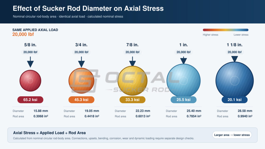
The following calculation uses nominal rod-body area and an axial load of 20,000 lbf. It illustrates the effect of diameter only; it does not represent a complete rod-string load case.
| Rod diameter | Nominal body area | Axial stress at 20,000 lbf | Percentage of Grade C/K minimum yield strength | Percentage of Grade D minimum yield strength |
|---|---|---|---|---|
| 5/8 in. | 0.3068 in² | 65.2 ksi | 108.7% | 76.7% |
| 3/4 in. | 0.4418 in² | 45.3 ksi | 75.5% | 53.3% |
| 7/8 in. | 0.6013 in² | 33.3 ksi | 55.5% | 39.2% |
| 1 in. | 0.7854 in² | 25.5 ksi | 42.5% | 30.0% |
| 1 1/8 in. | 0.9940 in² | 20.1 ksi | 33.5% | 23.7% |
This comparison shows why grade and diameter cannot be considered separately. Increasing strength may support a higher axial load, while increasing diameter reduces stress directly and also increases the suspended weight of the string.
A tapered string places larger or higher-strength rods near the top, where the rod must carry its own weight plus the fluid and dynamic loads below. Lower sections may use smaller rods where the calculated load permits.
Yield Load Is Not the Working Load
Multiplying nominal area by minimum yield strength gives a useful material reference, but it does not provide an allowable operating or pulling load.
| Rod diameter | Theoretical load at 60 ksi minimum yield for Grade C/K | Theoretical load at 85 ksi minimum yield for Grade D |
|---|---|---|
| 5/8 in. | 18.4 klbf / 81.9 kN | 26.1 klbf / 116.0 kN |
| 3/4 in. | 26.5 klbf / 117.9 kN | 37.6 klbf / 167.1 kN |
| 7/8 in. | 36.1 klbf / 160.5 kN | 51.1 klbf / 227.3 kN |
| 1 in. | 47.1 klbf / 209.6 kN | 66.8 klbf / 297.0 kN |
| 1 1/8 in. | 59.6 klbf / 265.3 kN | 84.5 klbf / 375.9 kN |
These values are based on the nominal rod body. Actual allowable pull must account for the smallest effective section, connection capacity, corrosion loss, wear, bending and the condition of reused rods.
Published maximum pulling-force tables commonly apply an additional margin to new or like-new rods. That margin must not be transferred automatically to a worn rod string because pits and localized section loss create stress concentrations that a simple area calculation cannot represent.
Cyclic Stress and the Modified Goodman Method
A pumping rod experiences maximum and minimum tensile stress during every stroke. The stress range and mean stress govern fatigue demand more directly than maximum load alone.
The modified Goodman relationship is commonly used as a screening method for beam-pumping applications:
| Symbol | Meaning | Required unit consistency |
|---|---|---|
| Maximum allowable stress from the selected design relationship | ksi or MPa | |
| Specified minimum tensile strength of the selected grade | Same stress unit | |
| Minimum calculated or measured stress during the pumping cycle | Same stress unit | |
| Selected service factor | Dimensionless | |
| 0.5625 | Slope coefficient used in the conventional modified Goodman relationship | Dimensionless |
The following example uses the minimum tensile strength of the two grade groups and a service factor of 0.90. It illustrates the calculation method rather than establishing a universal operating limit.
| Minimum cyclic stress | Grade C/K allowable maximum stress using 90 ksi minimum tensile strength | Grade D allowable maximum stress using 115 ksi minimum tensile strength |
|---|---|---|
| 0 ksi | 20.3 ksi | 25.9 ksi |
| 10 ksi | 25.3 ksi | 30.9 ksi |
| 20 ksi | 30.4 ksi | 36.0 ksi |
| 30 ksi | 35.4 ksi | 41.1 ksi |
The applicable service factor depends on well environment, operating history, load uncertainty and the operator’s design practice. A calculated point below the Goodman line still requires checks for buckling, compression, connection loading, rod-to-tubing contact and corrosion fatigue.
Progressive cavity pump applications also transmit torque. In that case, axial stress alone is insufficient, and the design must evaluate combined axial and torsional stress using an approved method.
Why Surface Loss Matters
A reduction in rod diameter increases nominal stress even when the polished-rod load remains unchanged. Because area changes with the square of diameter, a small diameter loss produces a larger percentage loss of load-bearing area.
The following example uses a nominal 7/8 in. rod under an axial load of 20,000 lbf and assumes uniform diameter loss. Localized pits are more severe than this calculation because they also concentrate stress.
| Remaining diameter | Diameter loss | Remaining area | Area loss | Calculated axial stress |
|---|---|---|---|---|
| 0.875 in. | 0% | 0.6013 in² | 0% | 33.3 ksi |
| 0.831 in. | 5% | 0.5427 in² | 9.8% | 36.9 ksi |
| 0.788 in. | 10% | 0.4871 in² | 19.0% | 41.1 ksi |
Uniform wear measurements cannot fully describe pit severity. Inspection should also record pit depth, pit location, circumferential wear, mechanical scoring, upset condition and thread damage.
Corrosion and Fatigue Cannot Be Rated by Grade Alone
Fatigue cracks commonly initiate at locations where local stress exceeds the nominal rod-body calculation. Corrosion pits, wrench marks, forged transitions, thread roots and rod-to-tubing contact areas require particular attention.
| Condition | Data needed for evaluation | Effect on rod performance |
|---|---|---|
| CO₂ exposure | Partial pressure, water chemistry, temperature, pH and inhibitor residual | Can produce localized or general carbon-dioxide corrosion |
| H₂S exposure | Partial pressure, pH, chloride content, hardness and applied stress | Can increase hydrogen-related cracking risk |
| Chloride-bearing water | Chloride concentration, temperature and dissolved oxygen | Accelerates localized attack and can reduce inhibitor performance |
| Microbiological activity | Bacterial count, water source and deposit condition | May produce localized corrosion beneath deposits |
| Sand production | Solids concentration, particle size and flow velocity | Increases abrasive wear at contact and flow-disturbed areas |
| Deviated well geometry | Inclination, dogleg severity, contact force and guide spacing | Increases bending stress and rod-to-tubing wear |
| Chemical inhibition | Inhibitor type, dosage, injection point and measured residual | Determines whether the assumed corrosion-control condition is actually maintained |
API compliance confirms standardized material and mechanical requirements. It does not provide a guaranteed corrosion rate, fatigue life or run time for a specific well. Claims such as a fixed number of fatigue cycles are meaningful only when the specimen geometry, surface finish, stress ratio, environment and test method are stated.
Inspection Data That Should Accompany Mechanical Compliance
Mechanical-property acceptance begins with a qualified tensile test, but a compliant rod also requires dimensional, connection and surface verification.
| Inspection item | Acceptance basis | Evidence to review |
|---|---|---|
| Material identity | Correct API grade and specified steel family | Heat number, grade marking and material certificate |
| Yield strength | At or above the applicable grade minimum | Tensile-test report showing the test method and specimen identification |
| Tensile strength | Within the specified grade range | Tensile-test report linked to the production heat or lot |
| Elongation | At or above the applicable minimum | Recorded gauge length and measured elongation |
| Reduction of area | At or above the applicable minimum | Original and final specimen dimensions |
| Rod-body diameter | Within the dimensional tolerance of the applicable API specification | Calibrated dimensional-inspection record |
| Rod length | Correct ordered nominal length and applicable length tolerance | Final inspection report |
| Thread geometry | Passes the specified API working-gauge inspection | Gauge identification and calibration status |
| Shoulder and wrench square | Conforms to the applicable drawing and dimensional requirements | Dimensional inspection record |
| Raw-material soundness | Electromagnetic or ultrasonic inspection according to the qualified manufacturing route | NDT report, calibration reference and disposition of indications |
| Surface condition | Free from rejectable laps, cracks, injurious seams and handling damage | Visual inspection and documented repair or rejection record |
| Traceability | Rod marking remains linked to heat and manufacturing lot | Heat/lot map, test reports and packing list |
A hardness result should be used as supporting evidence for heat-treatment consistency. Unless the purchase specification defines a hardness range for the selected product, it should not be presented as the sole API acceptance criterion.
Practical Grade Selection Sequence
A technically complete selection process should proceed from measured or calculated well conditions:
- Calculate maximum and minimum load through the full pumping cycle.
- Convert sectional loads to stress using the effective area of each rod size.
- Evaluate fatigue demand with the approved design method and service factor.
- Check the connection and upset section separately from the nominal rod body.
- Include rod weight, fluid load, buoyancy, acceleration and pump load.
- Evaluate bending and contact forces in deviated intervals.
- Review CO₂, H₂S, chloride, water cut, temperature, solids and inhibitor data.
- Select the grade and diameter taper together.
- Recalculate the design using the actual manufacturer’s minimum properties.
- Define inspection and retirement criteria for rods returned from service.
This sequence prevents the grade name from becoming a substitute for engineering. A high-strength rod can still fail from corrosion fatigue, while a corrosion-oriented grade can still be overloaded by an unsuitable string design.
FAQ
Q: What is the main mechanical difference between Grade C, Grade K and Grade D sucker rods?
A: Grade C and Grade K have a minimum yield strength of 60 ksi and a tensile range of 90–115 ksi. The Grade D family starts at a minimum yield strength of 85 ksi and uses a tensile range of 115–140 ksi. Grade K differs from Grade C mainly through alloy classification and corrosion-oriented service positioning.
Q: Does Grade K have greater tensile strength than Grade C?
A: No. Their basic API mechanical ranges are the same. Grade K uses an alloy-steel material system intended for corrosion-oriented light-to-moderate-load service, while Grade C uses carbon or carbon-manganese steel.
Q: Are all Grade D sucker rods made from the same steel?
A: No. Current grade identification may distinguish DC carbon steel, DA alloy steel and DS special-alloy steel. The purchase specification should state the exact grade designation, required mechanical properties, material basis and identification color.
Q: Can minimum yield strength be used as the allowable working stress?
A: No. Yield strength is a material acceptance property. Allowable working stress must include cyclic maximum and minimum stress, service factor, fatigue criterion, connection area, corrosion loss, wear, deviation and the condition of the installed rod string.