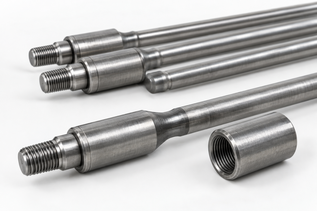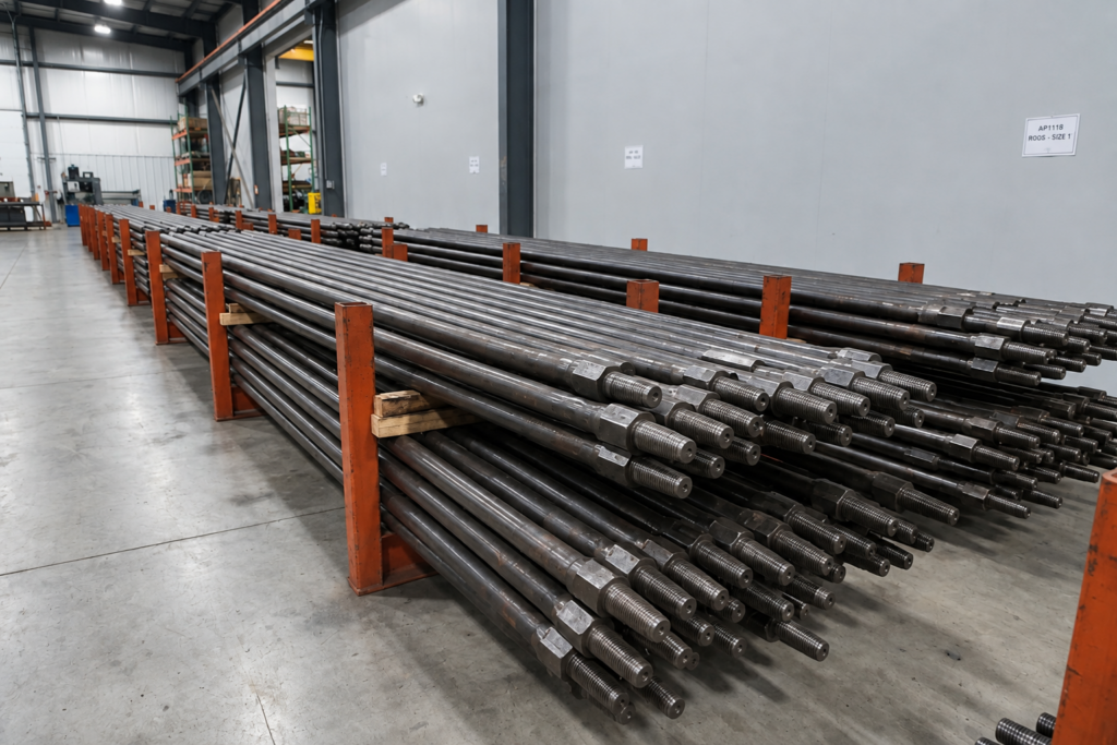
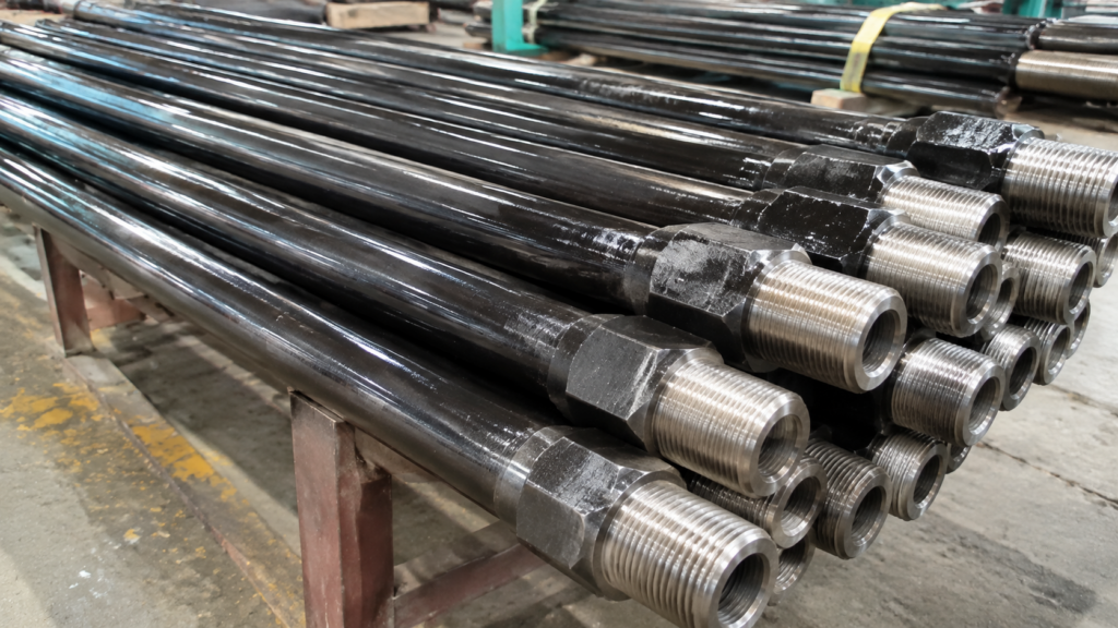
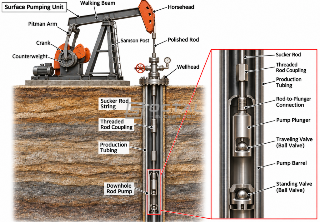
A sucker rod string consists of individual steel rods connected by threaded couplings and installed inside the production tubing to transmit reciprocating motion from the surface pumping unit to the downhole rod pump. During operation, the rod string moves with the pump through repeated upstroke and downstroke cycles, carrying the loads generated by the suspended rod weight, produced fluid and pump operation. Although sucker rods are primarily designed to withstand tensile loading, certain operating conditions can also introduce compression into the lower sections of the string. When this compression causes a rod section to bend laterally inside the tubing, the resulting mechanical instability is known as sucker rod buckling.
The consequences of buckling extend beyond the deformation of the rod itself. As the rod string moves away from its normal alignment, it may come into contact with the production tubing, increasing friction and creating additional bending stress. Repeated contact can cause localized wear on the rod body, couplings and tubing, potentially leading to fatigue damage, component failure or tubing leakage. These problems can increase workover requirements and affect the reliability of the entire pumping system. Understanding the forces that contribute to buckling and the conditions that influence rod-string stability is therefore essential for proper sucker rod system design and maintenance.
What Causes Sucker Rod Buckling?
The forces acting on a sucker rod string change throughout each pumping cycle. During the upstroke, the surface pumping unit lifts the rod string and the fluid load, causing the rods to carry tensile forces. During the downstroke, the rod string and plunger move downward, but their movement is resisted by several forces generated within the pump and surrounding fluid. Pressure differences across the pump valves, fluid-flow resistance and mechanical friction can oppose the downward movement and contribute to compression in the lower rod sections.
The magnitude and distribution of these forces depend on the pump configuration, fluid properties, pumping conditions and rod-string arrangement. Wellbore geometry and contact between the rod string and production tubing can further influence how the loads are transferred along the string. To understand where compression develops and why certain rod sections are more susceptible to instability, it is necessary to examine the individual forces involved in the pumping process.
Downstroke Compression in the Rod String
During the upstroke, the surface pumping unit pulls the sucker rod string upward. The rods support their suspended weight and transmit the load required to lift the produced fluid through the pumping system. This generally places the rod string under tensile loading.
The loading condition changes during the downstroke. As the pumping unit moves the rod string and plunger downward, the plunger encounters resistance from the fluid inside the pump. The pressure difference across the traveling valve, fluid-flow resistance and mechanical friction can oppose the downward movement. These forces may generate an upward reaction at the lower end of the rod string, contributing to axial compression in the rod sections above the pump.
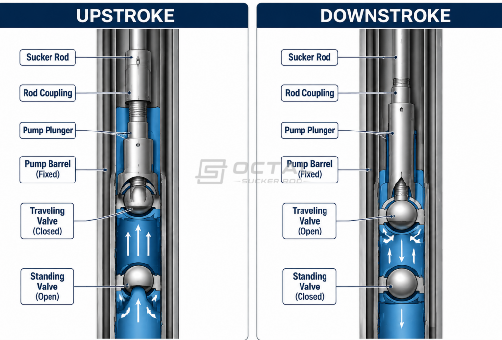
Compression is not necessarily distributed uniformly throughout the rod string. Its magnitude at different depths depends on the forces acting near the pump, the weight of the rod sections, fluid conditions and the mechanical characteristics of the assembly. The lower sections are particularly important because they are closest to the pump and may experience the compressive forces transmitted from the pump mechanism.
For this reason, evaluating buckling risk requires more than calculating the total suspended weight of the rod string. Engineers must determine how the axial load changes along the rod string and how the loading condition varies between the upstroke and downstroke.
Pressure Differential Across the Traveling Valve
The traveling valve is located inside the pump plunger and controls fluid movement between the lower and upper chambers of the pump barrel. During the downstroke, the pressure below the plunger increases relative to the pressure above it, allowing the traveling valve to open and fluid to pass through the plunger.
As fluid flows through the valve opening, a pressure drop develops across the valve. The pressure difference acting over the effective plunger area also generates a hydraulic force that influences plunger movement. When this force opposes the downward stroke, it contributes to the load transmitted through the sucker rod string.
Several operating variables affect this hydraulic resistance:
- Pressure Differential: The pressure difference across the traveling valve influences the hydraulic force acting on the plunger.
- Traveling Valve Flow Area: A restricted flow opening can increase pressure loss as fluid passes through the valve.
- Fluid Viscosity: Higher-viscosity fluids generally create greater resistance to flow.
- Pumping Speed: Higher plunger velocity can increase flow-related pressure losses.
- Valve Condition: Deposits, restricted openings or mechanical damage can affect valve performance and fluid passage.
These factors should be considered when investigating excessive downstroke loading. A rod string may have sufficient tensile strength for normal operation but still experience unfavorable compression if hydraulic resistance inside the pump is not properly accounted for.
Plunger Friction and Fluid Resistance
Besides hydraulic resistance across the traveling valve, mechanical friction between the plunger and pump barrel can also influence the downstroke load.
The plunger moves inside the pump barrel with a specified clearance that allows reciprocating movement while limiting fluid leakage. Excessive contact, surface damage, deposits or unsuitable clearance can increase friction and the force required to move the plunger.
Fluid resistance also develops as produced fluid passes through the pump passages and valve openings. Its magnitude depends on fluid viscosity, flow velocity, pump geometry and operating conditions.
When these mechanical and hydraulic forces oppose downward movement, they can increase the compressive loading transmitted to the lower rod sections. High-viscosity production fluids and restricted pump passages deserve particular attention, although viscosity alone cannot determine the actual buckling risk. The pump condition, pumping speed and complete rod-string load distribution must also be evaluated.
Well Deviation and Rod-to-Tubing Contact
The forces generated by the pump explain how compression can develop, but the geometry of the well also affects how the rod string behaves under these loads.
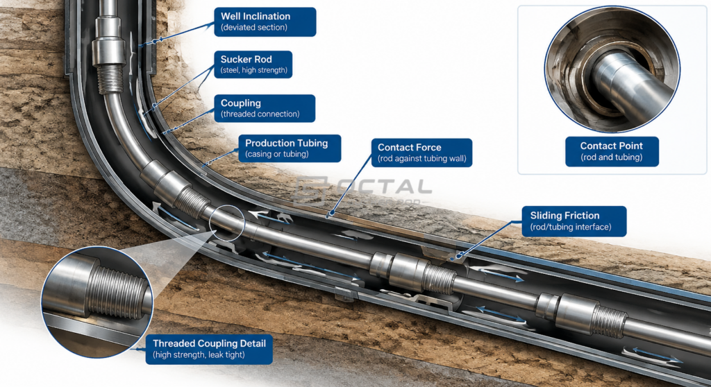
In a vertical well, the rod string is primarily influenced by its suspended weight and the forces generated by the downhole pump. In a deviated well, gravity and changes in wellbore direction can cause the rods and couplings to contact the production tubing. This contact creates lateral reaction forces and friction during reciprocating movement.
The degree of contact depends on several factors:
| Factor | Effect on the Rod String |
| Well Inclination | Changes the direction and magnitude of gravity-related side loading |
| Dogleg Severity | Influences rod curvature and localized contact |
| Rod-Body Diameter | Affects bending stiffness and radial clearance |
| Coupling Outside Diameter | Determines the maximum connection envelope inside the tubing |
| Tubing Inside Diameter | Defines the available space for rod movement |
| Pumping Movement | Produces repeated sliding contact and friction |
It is important to distinguish between the forces that generate axial compression and the conditions that influence lateral deformation. Well deviation and tubing contact do not automatically cause buckling. However, they change the lateral support, friction and contact conditions under which a compressed rod section must operate.
This is why the same rod-string configuration may behave differently in vertical and deviated wells, even when the calculated axial loads are similar.
How Does the Neutral Point Affect Sucker Rod Buckling?
After identifying the forces that can create compression, the next step is to determine where the compressive condition develops along the rod string. This is where the Neutral Point becomes important.
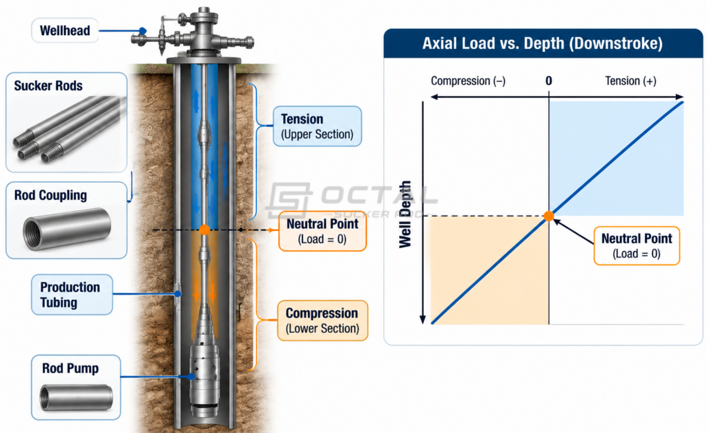
The neutral point is the position along the rod string where the calculated axial load changes from tension to compression under a specified pumping condition and load convention. Above this position, the rod sections generally carry tensile load. Below it, the calculated load may become compressive.
The neutral point is not a fixed position. It changes with the pumping cycle because the axial forces acting on the rod string change during the upstroke and downstroke. Pump pressure, fluid resistance, rod-string weight and operating speed can all affect its location.
The practical importance of the neutral point is that it identifies the part of the rod string that requires closer evaluation for compression-related instability. If a significant rod section below the neutral point is subjected to compression, engineers must determine whether its bending stiffness and lateral support are sufficient for the applied load.
True Load and Effective Load
Two load terms are often used in sucker rod analysis: True Load and Effective Load. They describe different aspects of the rod-string loading and should not be treated as interchangeable.
True Load refers to the actual mechanical axial force carried by a rod section under the selected calculation convention. It is used to evaluate the nominal axial stress in the rod body.
Effective Load is a calculated load that incorporates the applicable pressure and buoyancy corrections in the selected engineering model. These corrections account for the influence of the surrounding fluid and pressure conditions on the rod string’s effective loading state.
| Load Term | Meaning | Main Engineering Use |
| True Load | Mechanical axial force carried by the rod section | Evaluating nominal rod-body axial stress |
| Effective Load | Load adjusted for applicable pressure and buoyancy effects | Evaluating effective tension and compression |
| Maximum Load | Highest tensile load during the pumping cycle | Strength and fatigue assessment |
| Minimum Load | Lowest load during the pumping cycle | Identifying possible compression conditions |
The exact definitions and sign conventions can vary between calculation methods and rod-pumping software. Therefore, the selected model must be identified before comparing load values or determining the neutral point.
For buckling assessment, the relevant compressive force must be compared with the buckling resistance of the rod section under its actual support and contact conditions. Buoyancy changes the effective load distribution, but it should not be treated as an independent force that automatically causes buckling.
Why Does Rod Diameter Affect Buckling Resistance?
Rod diameter directly affects how well a sucker rod resists bending under compression. A larger-diameter rod is generally stiffer and less likely to bend sideways than a smaller-diameter rod made from the same material.
For a solid circular rod, its bending resistance is related to the second moment of area:
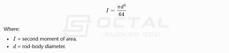
The diameter is raised to the fourth power in this equation. This means that even a relatively small increase in rod diameter can significantly improve its bending stiffness.
However, larger rods also weigh more, increasing the load carried by the upper sections of the rod string. Therefore, rod diameter should be selected by considering both buckling resistance and the overall load distribution, rather than simply choosing the largest available size.
What Are the Two Main Types of Sucker Rod Buckling?
After compression develops, the rod string may no longer remain in its original straight configuration. Because the production tubing restricts lateral movement, the rod cannot deform freely in every direction. Instead, it develops specific bending patterns within the available space.
Two commonly discussed configurations are Sinusoidal Buckling and Helical Buckling. They describe different deformation patterns of a slender rod confined inside a cylindrical tube.
Sinusoidal Buckling
Sinusoidal buckling occurs when a compressed rod section develops a wave-like lateral deformation inside the tubing. The rod moves away from its original centerline and forms alternating curves along its length.
The deformation is influenced by the compressive force, rod stiffness, tubing clearance and the length of the rod section between effective lateral supports.
Although the rod remains confined within the tubing, its curved configuration creates additional bending stress. If the rod continues to move under repeated pumping cycles, the contact position may change, resulting in repeated friction against the tubing wall.
Sinusoidal buckling is therefore important even when the deformation appears relatively small. Localized bending and repeated contact can contribute to fatigue damage, particularly near rod-end transitions and other geometric discontinuities.
Helical Buckling
Helical buckling is a more developed three-dimensional deformation in which the compressed rod forms a spiral configuration inside the tubing.
Unlike the wave-like pattern of sinusoidal buckling, the rod follows a helical path around the tubing’s internal space. This configuration can create more extensive contact between the rod string and tubing wall, depending on the compressive load and available clearance.
The resulting contact forces may increase frictional resistance and local wear. The rod body and coupling can experience repeated contact, while the tubing may develop localized wear marks along the affected section.
Under idealized axial compression, a confined slender rod may progress from an initially straight configuration to sinusoidal buckling and then to helical buckling. However, an actual sucker rod string does not necessarily follow this sequence uniformly. Wellbore inclination, changing support conditions, dynamic loading and tubing contact can produce different deformation patterns along the same string.
Sinusoidal vs. Helical Buckling
| Comparison | Sinusoidal Buckling | Helical Buckling |
| Deformation pattern | Wave-like lateral bending | Three-dimensional spiral deformation |
| Main mechanical feature | Alternating lateral curves | Helical movement around the tubing space |
| Contact behavior | Localized or intermittent contact | Potentially more extensive contact |
| Main concern | Bending stress and localized wear | Bending stress, friction and contact wear |
| Engineering assessment | Compression, stiffness and lateral support | Compression, tubing confinement and contact conditions |
The distinction between these two configurations helps engineers understand how a rod string responds to compression. However, identifying the deformation pattern alone is not enough to determine the severity of the problem. Its effect on the rod, coupling and tubing must also be evaluated.
What Problems Can Sucker Rod Buckling Cause?
Once a rod section buckles, the resulting lateral deformation changes the way the rod string moves inside the production tubing. The additional contact forces can affect several components of the pumping system, not just the section where the initial deformation occurs.
Rod Body Bending and Fatigue Damage
A straight rod body primarily carries axial loading. When the rod bends laterally, it also experiences bending stress.
The total stress condition therefore becomes more complex than a simple tensile or compressive load calculation. The combination of axial stress and bending stress can increase the local stress range during repeated pumping cycles.
This is particularly important near the upset transition, where the slender rod body changes into a larger forged end. The change in cross-sectional geometry affects the distribution of bending stress and may create a fatigue-sensitive location.
If the rod also contains surface defects, corrosion pits or existing mechanical damage, fatigue cracks may develop more readily under repeated loading.
The resulting failure may appear as a rod-body fracture even though the original problem involved compression and lateral instability.
Sucker Rod Coupling Wear
Sucker rod couplings have a larger outside diameter than the rod body. When the rod string moves laterally inside the tubing, the coupling may become one of the first components to contact the tubing wall.
Repeated contact can gradually remove material from the coupling’s outside surface. This reduces the remaining wear allowance and may expose the coupling to more severe mechanical damage.
Coupling wear is especially relevant in deviated wells, where rod-to-tubing contact may occur repeatedly at predictable positions along the well trajectory.
The coupling’s outside diameter, hardness, wear characteristics and tubing clearance should therefore be considered when evaluating the overall rod-string design.
Production Tubing Wear and Leakage
The production tubing can also suffer from repeated contact with a buckled rod string or its couplings.
As the rod assembly reciprocates, friction removes material from the tubing’s internal surface. Over time, the resulting wall thinning may reduce the tubing’s ability to withstand the required internal pressure.
If wear becomes severe enough, the tubing may develop a leak. This can lead to loss of production efficiency, additional well intervention and tubing replacement.
The location and pattern of tubing wear can also provide useful information during failure investigation. Comparing the damaged tubing with the pulled rod string and coupling condition helps engineers identify possible contact locations and assess whether buckling contributed to the damage.
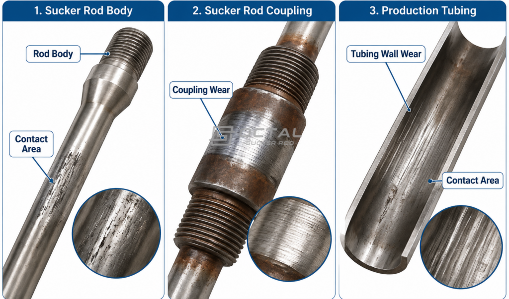
Increased Friction and Loss of Pumping Efficiency
Buckling also affects the energy required to move the rod string.
When the rod contacts the tubing, additional friction develops during reciprocating movement. Part of the surface pumping unit’s mechanical energy is then consumed in overcoming this resistance rather than driving the downhole pump.
The result may include increased mechanical loading, reduced effective stroke at the pump and additional wear at contact locations.
The actual impact depends on the degree of deformation, contact force, friction characteristics and operating conditions. Buckling should therefore be assessed as both a mechanical stability issue and a potential source of pumping-system energy loss.
How Can Sucker Rod Buckling Be Evaluated?
Identifying the possible causes of buckling is only the first step. A reliable engineering assessment must determine where compression develops, how large the compressive force becomes and whether the rod section can remain stable under the actual tubing constraints.
A simple comparison between the total rod-string weight and the rod’s tensile strength cannot provide this information.
Axial Load Distribution Along the Rod String
The first step in buckling assessment is to calculate the axial load at different depths throughout the pumping cycle. For a tapered rod string, each section has a different diameter, weight and bending stiffness, so the load must be evaluated separately.
The calculation should identify:
- Maximum and minimum axial loads in each rod section.
- Location of the neutral point.
- Length of the rod string under compression.
- Compressive force near the downhole pump.
These results help identify which rod sections require further buckling analysis.
Critical Buckling Load and Factors Affecting Rod Stability
The critical buckling load refers to the compressive force at which a rod section can no longer maintain its straight shape and begins to bend laterally. Whether buckling occurs depends on the relationship between the applied compressive force and the rod’s resistance to bending.
Several factors influence this resistance:
| Factor | Effect on Buckling Resistance |
| Rod Diameter | Larger diameters provide greater bending stiffness. |
| Unsupported Length | Shorter unsupported sections generally have better stability. |
| Material Elastic Modulus | Higher elastic modulus increases bending stiffness. |
| Lateral Support | Proper support helps limit sideways deformation. |
| Tubing Clearance | Available clearance affects the rod’s lateral movement and contact behavior. |
For this reason, engineers should evaluate the compressive load together with the rod diameter, section length and downhole support conditions. A rod section is more susceptible to buckling when the applied compression exceeds its resistance to lateral deformation.
Dynamometer Card Analysis
A dynamometer card records the relationship between polished rod load and displacement during a pumping cycle.
It provides useful information about the surface loading behavior and can help identify abnormal pumping conditions that may contribute to unfavorable rod-string loading.
For example, abnormal load patterns may indicate changes in pump filling, valve operation, fluid interference or mechanical resistance.
However, a surface dynamometer card measures the load at the polished rod. It does not directly show the exact compressive force or buckling shape at every depth in the well.
To evaluate downhole buckling, the surface measurements should be combined with an appropriate rod-string model, pump operating data and wellbore geometry. Where available, downhole dynamometer measurements can provide additional information about the load near the pump.
Well Trajectory and Tubing Clearance
The final part of the assessment is to determine how the rod string is supported and constrained inside the well.
The following information is particularly important:
| Required Information | Why It Matters |
| Rod diameter and section length | Determines rod weight and bending stiffness |
| Rod material properties | Establishes elastic modulus and strength limits |
| Tubing inside diameter | Defines available radial clearance |
| Coupling outside diameter | Determines the maximum connection envelope |
| Well deviation survey | Identifies inclined sections and dogleg severity |
| Pump operating conditions | Establishes downstroke forces and pressure differences |
| Fluid density and viscosity | Supports buoyancy and fluid-resistance calculations |
| Pumping speed and stroke length | Defines reciprocating motion and dynamic loading |
| Existing rod guide positions | Identifies lateral support locations |
| Previous failure and wear records | Helps identify recurring contact and damage locations |
For wells with significant deviation or complex rod-string configurations, a three-dimensional dynamic model or finite element analysis may be necessary.
These methods can simulate rod deformation under changing loads and evaluate where the rod string contacts the tubing. They are particularly useful when conventional calculations cannot adequately represent the actual wellbore geometry.
How Can Sucker Rod Buckling Be Prevented?
Sucker rod buckling can be controlled by reducing excessive compression and improving the mechanical stability of the rod string. The main measures involve adjusting rod-string weight and diameter, controlling lateral movement and optimizing pump operating conditions.
| Prevention Method | How It Helps | Key Design Consideration |
| Sinker Bars | Add weight near the downhole pump to help maintain tension in the upper rod sections. | Sinker bar weight, length, diameter and buckling resistance. |
| Rod Diameter Optimization | Larger-diameter rods provide greater bending stiffness and resistance to lateral deformation. | Balance buckling resistance against additional rod-string weight. |
| Tapered Rod String | Uses different rod diameters to match the changing load conditions along the well. | Select suitable diameters and section lengths based on load calculations. |
| Sucker Rod Guides | Reduce direct contact between rod couplings and production tubing. | Guide spacing, wear resistance and tubing clearance. |
| Pump Optimization | Reduces unnecessary hydraulic resistance and mechanical friction during the downstroke. | Traveling valve condition, plunger clearance and pumping speed. |
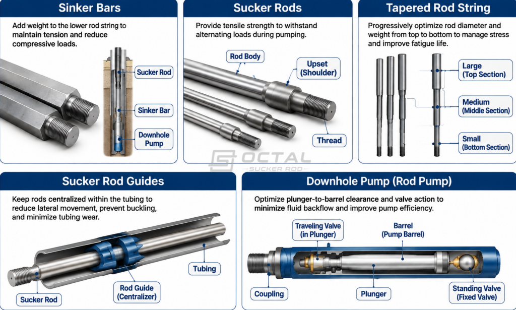
These measures serve different purposes and should be selected according to actual well conditions. Sinker bars help control axial loading, rod guides reduce contact wear, and proper rod-string design improves mechanical stability. Combining these measures with accurate load calculations helps reduce buckling risk and extend the service life of the pumping system.
Conclusion
Sucker rod buckling is closely related to axial compression, rod-string configuration and downhole operating conditions. Proper load analysis, suitable rod diameters, sinker bars and rod guides can help reduce buckling risk, control tubing wear and improve pumping system reliability.
Octal Sucker Rod focuses on API 11B sucker rods and related rod-lift components, including high-strength sucker rods, pony rods, polished rods, sinker bars and sucker rod couplings. We assist customers with product selection, rod diameter and grade matching, connection configuration, manufacturing coordination, inspection documentation and export delivery. By reviewing product specifications against actual well requirements, we help customers select suitable rod-string components for their pumping applications.
FAQ
1. Does sucker rod buckling mainly occur during the downstroke?
Buckling risk is generally concentrated in the lower rod sections during the downstroke, when pump-related hydraulic forces and mechanical resistance can create axial compression. The actual loading condition should be evaluated throughout the pumping cycle.
2. What is the difference between sinusoidal and helical sucker rod buckling?
Sinusoidal buckling produces wave-like lateral deformation, while helical buckling produces a three-dimensional spiral configuration inside the tubing. Both can increase bending stress and rod-to-tubing contact, but their deformation patterns and contact conditions are different.
3. Can sucker rod guides completely prevent buckling?
No. Sucker rod guides provide lateral support and reduce direct contact between the rod string and tubing. They do not eliminate axial compression, so proper load calculations and rod-string design remain necessary.
No. Sucker rod guides provide lateral support and reduce direct contact between the rod string and tubing. They do not eliminate axial compression, so proper load calculations and rod-string design remain necessary.
4. Do sinker bars prevent sucker rod buckling?
Properly designed sinker bars add weight near the downhole pump and help maintain tensile loading in the conventional rod sections above them. Their own compressive stability, tubing clearance and effect on the overall rod-string load must also be evaluated.
5. Does using a higher-strength sucker rod grade reduce buckling risk?
Not necessarily. Higher tensile strength increases the material’s resistance to tensile and yielding-related failure, but elastic buckling is mainly governed by elastic modulus, rod diameter, unsupported length, applied compression and lateral support conditions. Selecting a higher grade alone is not a substitute for buckling analysis.