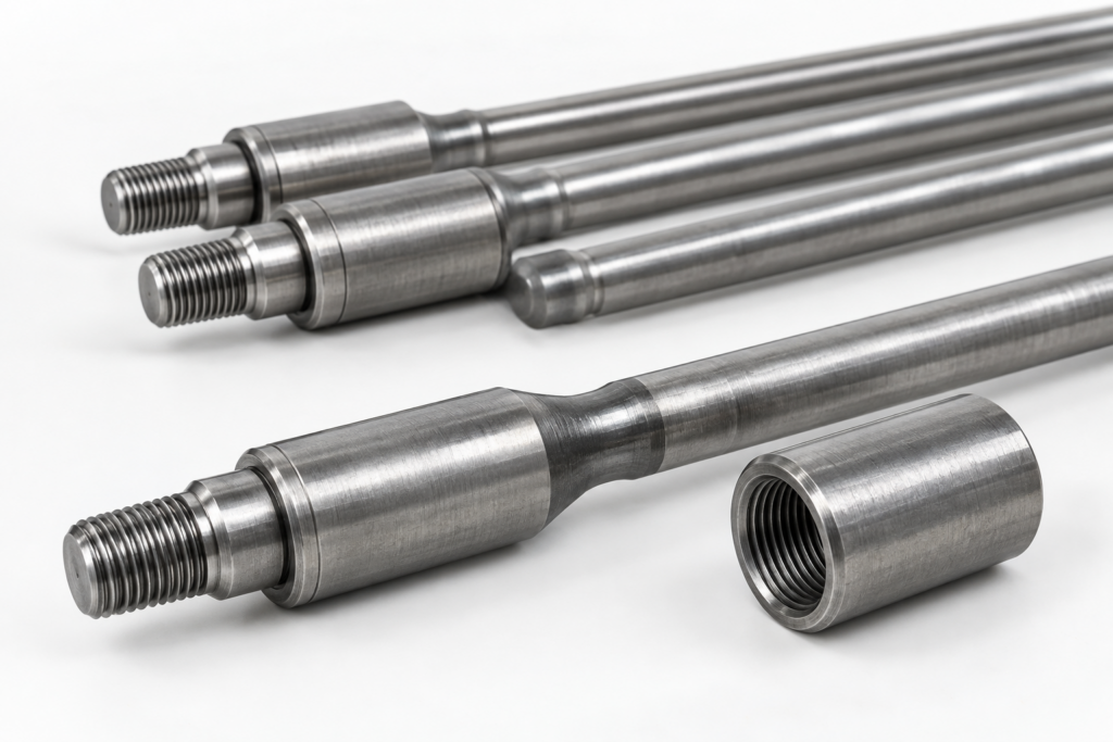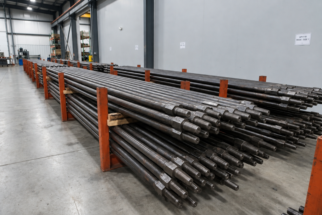
Sucker Rod Pump Spacing determines the axial position of the downhole plunger relative to the stationary pump barrel and standing-valve assembly at the lower end of the pumping stroke. The surface pumping unit transfers reciprocating motion through the polished rod and sucker rod string to drive the plunger. During the upstroke, the traveling valve closes and the standing valve opens, allowing formation fluid to enter the pump barrel. During the downstroke, the standing valve closes and the traveling valve opens, allowing fluid below the plunger to pass into the production tubing. Proper spacing maintains the specified mechanical clearance at the bottom of the stroke, preventing the plunger from contacting the standing-valve assembly while limiting unnecessary clearance volume inside the pump.
The correct setting requires consideration of sucker rod elongation under load, tubing movement, pump setting depth, fluid loading, pumping speed and downhole operating conditions. Excessive spacing increases the unswept volume below the plunger, reducing the pump’s geometric compression ratio and potentially affecting gas compression and volumetric efficiency. Insufficient spacing can cause pump tagging when rod-string movement or dynamic overtravel brings the plunger into contact with the standing-valve assembly. These effects become more significant in deep wells and installations using fiberglass or tapered sucker rod strings, where differences in rod elasticity and string configuration must be included in the space-out calculation.

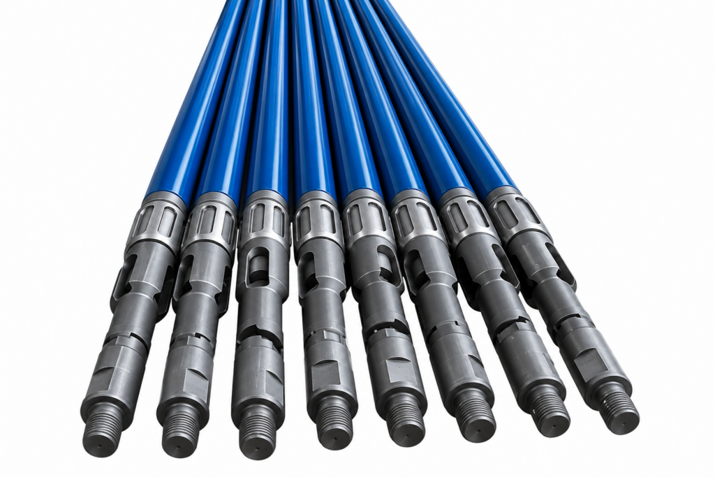
Factors Affecting Sucker Rod Pump Spacing
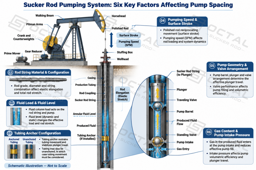
Sucker rod pump spacing is affected by the combined mechanical and operating conditions of the entire pumping system. Six factors need to be considered: rod string material and configuration, fluid load and fluid level, tubing anchor configuration, pumping speed and surface stroke length, downhole pump geometry, and gas content at the pump intake. Each factor influences either the elastic movement of the rod string, the axial position of the pump barrel, the actual plunger travel, or the volume that must be compressed inside the pump. If these effects are underestimated, the plunger may contact the standing-valve assembly during the downstroke, or excessive clearance may reduce the pump’s compression ratio and impair gas handling.
Key Factors Affecting Pump Spacing
| Factor | What It Affects | Possible Consequence |
|---|---|---|
| Rod string material and configuration | Elastic elongation under axial load, based on rod material, diameter and section length | Incorrect plunger position and insufficient bottom clearance |
| Fluid load and fluid level | Rod-string loading, elastic stretch and pump intake pressure | Changes in downhole plunger position and gas compression requirements |
| Tubing anchor configuration | Axial movement and elongation of the tubing string and pump barrel | Incorrect allowance for relative movement between the plunger and barrel |
| Pumping speed and surface stroke length | Dynamic loading, plunger overtravel and actual downhole stroke | Pump tagging or an inaccurate estimate of operating clearance |
| Pump geometry and valve arrangement | Mechanical reference position, valve spacing and internal dead space | Insufficient mechanical clearance or reduced compression ratio |
| Gas content and pump intake pressure | Gas compression requirements before the traveling valve opens | Delayed valve opening, reduced pump fillage and gas interference |
Rod String Material and Configuration
Rod-string elongation is one of the main variables in a pump-spacing calculation. Under the fluid load, the sucker rod string stretches according to its material properties, cross-sectional area, length and applied axial force. A calculation based on the nominal rod size alone will not accurately represent a string containing different rod diameters or materials.
Steel and fiberglass sucker rods have significantly different elastic properties. Fiberglass generally undergoes greater elongation than steel under comparable loading conditions. A tapered rod string also requires section-by-section calculation because each rod diameter has a different cross-sectional area and elastic response. For a mixed-material string, the length and mechanical properties of each section must be included rather than applying one average stretch allowance.
The rod tally should identify the actual diameter, grade, material and length of each section. This includes API 11B sucker rods and any pony rods used to match the required string length. The connection type and condition of the sucker rod couplings should also be checked against the specified rod-end connections. These details establish the actual mechanical configuration used in the spacing assessment.
Fluid load and fluid level
Fluid load results from the pressure differential acting across the pump plunger. During the upstroke, the rod string carries the fluid load as the traveling valve closes and the standing valve opens. During the downstroke, the load transfers to the tubing as the standing valve closes and the traveling valve opens.
The magnitude of this load affects rod-string elongation and therefore the actual plunger position. Pump intake pressure also depends on the fluid column above the pump, while declining fluid levels can reduce intake pressure and increase the proportion of free gas entering the pump under certain well conditions.
A change in fluid level can therefore affect both the mechanical loading calculation and the pump’s gas-compression requirements. A spacing value established under an earlier production condition should be reassessed when fluid level or pumping conditions change significantly.
Tubing anchor configuration
The tubing string supports the stationary pump barrel in a conventional stationary-barrel installation. Its axial movement must be considered alongside rod-string elongation.
| Tubing Configuration | Mechanical Behavior | Effect on Pump Spacing |
|---|---|---|
| Anchored tubing | The anchor restricts axial tubing movement under normal operating conditions. | Tubing-stretch contribution is substantially reduced. |
| Unanchored tubing | The tubing elongates and contracts as the fluid load transfers during the pumping cycle. | Tubing movement must be included in the relative plunger-position calculation. |
| Slipping tubing anchor | The anchor does not maintain its intended position under operating loads. | Actual tubing movement may differ from the assumed anchored condition. |
For anchored tubing, the calculation should not automatically include the same tubing-stretch allowance used for an unanchored string. However, the anchor’s actual holding condition must be verified. A slipping anchor can change the relative movement between the pump barrel and plunger, even when the original installation calculation assumed that the tubing was fixed.
Pumping speed and surface stroke length
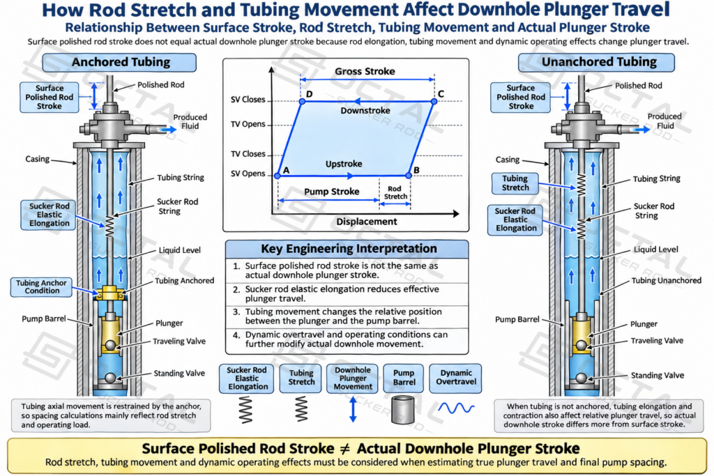
Surface stroke length does not equal the actual downhole plunger stroke. Rod elongation, tubing movement and dynamic effects all contribute to the difference.
As pumping speed increases, rod-string acceleration produces additional inertial forces. These forces can cause plunger overtravel, meaning the actual downhole plunger movement becomes greater than the value predicted from a static stretch calculation alone.
This difference is important when establishing bottom clearance. A setting that avoids mechanical contact at a lower pumping speed may become unsuitable after the unit operates faster. The actual operating speed, polished rod stroke length and expected dynamic overtravel should therefore be included in the assessment rather than treating surface stroke as the direct measurement of downhole movement.
Pump Geometry and Valve Arrangement
The internal geometry of the selected downhole sucker rod pump sets the mechanical reference for pump spacing. Plunger length and diameter, barrel dimensions, valve-rod or pull-tube length, and the relative positions of the standing and traveling valves together determine how much clearance remains at the bottom of the stroke and how much unswept volume stays inside the pump. This is why pump spacing cannot be established from polished-rod movement alone. Two pumps installed at the same depth may still require different spacing values if their internal dimensions, valve-cage geometry, or mechanical stop arrangement are different.
In practice, the spacing value must be based on the actual pump assembly dimensions and its design drawings, rather than a generalized field rule. A spacing allowance developed for one pump design should not be transferred directly to another without verifying the internal dead space, effective plunger travel, and lower-end mechanical reference position. This becomes particularly important when different sucker rod couplings, rod-string configurations, or downhole components affect the relationship between surface stroke and actual plunger position.
Gas Content and Pump Intake Pressure
Gas conditions are a critical part of sucker rod pump spacing because free gas inside the pump changes how the lower end of the stroke behaves. When gas enters the pump barrel, part of the plunger movement is used to compress that gas before the traveling valve can open normally. If the spacing is too large, the added dead space increases the gas volume that must be compressed, reduces the pump’s geometric compression ratio, and delays valve opening. Under low pump intake pressure or high free-gas conditions, this can reduce pump fillage, worsen gas interference, and in severe cases contribute to gas locking.
For that reason, spacing should always be evaluated together with intake pressure, discharge pressure, fluid level, plunger size, effective stroke length, and the gas-handling characteristics of the selected pump. The target is not simply to minimize spacing, but to keep enough mechanical clearance to avoid pump tagging while limiting unnecessary dead space. If a well is producing with significant gas, the final setting should be checked against actual operating conditions rather than relying only on installation dimensions, because acceptable spacing in a liquid-dominant well may be unsuitable once gas volume increases.
How to Space Out a Rod Pump: Step-by-Step Procedure
Proper sucker rod pump spacing begins with establishing a reliable mechanical reference point and determining how the rod string and downhole pump will move under operating loads. The setting process must account for the actual pump configuration, rod-string elasticity, tubing movement and expected pumping conditions. A spacing value based only on pump setting depth or a standard field allowance may result in insufficient mechanical clearance or excessive internal dead space.
The following procedure explains how to establish the pump reference position, determine the required spacing allowance, adjust the rod string and verify the final setting under operating conditions.
Step 1: Confirm the Pump and Rod String Configuration
Before establishing the pump spacing, confirm that the installed downhole assembly matches the well design. The pump dimensions, rod-string composition and tubing configuration determine the mechanical reference position and the amount of movement that must be accommodated during operation.
The following information should be collected and checked against the actual installation records.
| Required Information | Engineering Purpose |
|---|---|
| Pump type and configuration | Identifies the pump’s mechanical arrangement and reference points |
| Pump setting depth | Establishes the installed depth of the downhole assembly |
| Rod material and grade | Determines elastic properties and load capacity |
| Rod diameters and section lengths | Supports section-by-section stretch calculations |
| Tubing size and anchor condition | Determines whether tubing movement must be included |
| Pumping speed and surface stroke length | Establishes the expected operating and dynamic conditions |
| Fluid level and fluid load | Supports rod-load and buoyancy calculations |
| Pump internal dimensions | Identifies effective plunger travel and mechanical clearance requirements |
The actual rod-string tally should be checked against the installation records, including standard rod lengths, pony rod sections, coupling dimensions and connection types. For tapered strings, each rod section must be evaluated according to its actual diameter, material and installed length. These details are particularly important when the installation combines steel sucker rods, fiberglass sucker rods or different rod grades.
Step 2: Confirm Pump Seating and the Mechanical Reference
Before spacing out the rod string, confirm that the downhole pump has reached its intended installation position. For insert pumps, this includes verifying proper engagement with the seating nipple or hold-down assembly, where applicable. Other pump configurations must be checked against their corresponding landing and anchoring arrangements.
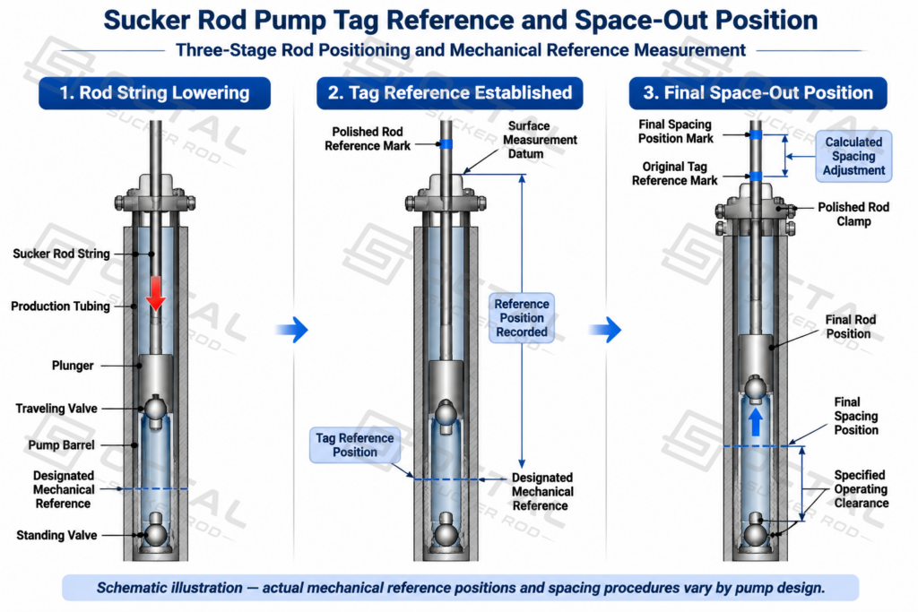
The lower mechanical reference must also be identified from the actual pump structure. Depending on the pump design, the reference may involve the plunger’s designated lower operating position, a specified valve-rod contact point or another defined mechanical stop. These positions should not be treated as interchangeable. An incorrect reference will affect every subsequent measurement and may result in an incorrect sucker rod pump spacing setting.
Step 3: Establish the Tag Reference
Once the pump position has been confirmed, establish a measurable reference for the rod string. Under the approved installation procedure, the rod string is carefully lowered under controlled conditions until the designated mechanical reference is identified. The corresponding polished rod or rod position is then marked and recorded as the tag reference.
The measurement should be repeated as necessary to confirm that the reference position is consistent. Rod-string friction, tubing movement and fluid loading can influence the measured position, so the actual measurement conditions must also be recorded. Where the installation procedure requires the tubing to be loaded or placed under a specified operating condition, the reference should be rechecked under that condition.
A tag reference is a measurement point, not an operating target. Hard impact, repeated pounding or using the pumping unit to force mechanical contact should not be used to establish pump spacing. This distinction is especially important with fiberglass sucker rods, which have different elastic behavior and can transmit damaging dynamic loads even when the surface indication of contact appears relatively mild.
Step 4: Calculate the Required Spacing Allowance
After establishing the tag reference, determine how far the rod string must be positioned above that reference to maintain adequate clearance throughout the pumping cycle. This adjustment is the calculated spacing allowance, and it must reflect the actual rod-string configuration and expected downhole operating conditions.
The main calculation considerations are summarized below.
| Calculation Factor | Engineering Consideration |
|---|---|
| Rod String Elongation | Elastic stretch of each rod section under the expected axial load |
| Tubing Movement | Tubing stretch or contraction, particularly in unanchored configurations |
| Fluid Loading and Buoyancy | Changes in rod loading and effective elongation under fluid conditions |
| Dynamic Overtravel | Additional downhole plunger movement caused by rod-string elasticity and pumping dynamics |
| Rod Material and Configuration | Differences in elastic behavior between steel, fiberglass and tapered rod strings |
| Mechanical Clearance | Required clearance based on the actual pump geometry and lower mechanical reference |
| Gas Compression | Effect of additional unswept volume on the pump’s compression ratio and gas handling |
These factors should not automatically be treated as independent distances that can simply be added together. Rod stretch, tubing movement and dynamic overtravel must be evaluated using a consistent calculation method to avoid double-counting. Gas compression is also a functional constraint: excessive spacing increases internal dead space and may reduce the pump’s ability to handle free gas, particularly at low intake pressure.
Step 5: Adjust the Rod String and Set the Polished Rod Clamp
Once the required spacing has been calculated, the rod string is raised or adjusted by the specified distance from the established reference position. The final rod-string length must correspond to the intended plunger position at the designated point in the pumping cycle.
Where the assembled rod-string length requires a short adjustment, a correctly sized pony rod can be incorporated. Its length, diameter, grade and connection type must match the adjacent rod sections and the actual connection arrangement. The dimensions and make-up condition of the sucker rod couplings should also be checked before the assembly is completed. A polished rod coupling must be used where required to connect the polished rod to the sucker rod or pony rod.
With the pumping unit positioned according to the installation procedure, the polished rod clamp is secured at the calculated setting position. The final rod position, pony rod length and connection arrangement should be recorded as part of the installation documentation. This record establishes the baseline for subsequent inspection and any future pump re-spacing work.
Step 6: Restart and Check the Operating Condition
After the spacing adjustment is completed, return the pumping unit to service according to the approved startup and well-control procedures. Initial operation should be monitored to determine whether the actual rod and pump movement agrees with the expected operating condition.
| Inspection Item | What to Check |
|---|---|
| Polished Rod Movement | Actual stroke behavior and smoothness of movement |
| Stroke Reversal | Unusual impact, load changes or irregular movement |
| Dynamometer Card | Load patterns indicating possible tagging, overtravel or gas interference |
| Pump Fillage | Changes in pump fillage and fluid displacement |
| Production Response | Fluid production and changes in operating performance |
| Mechanical Contact | Evidence of abnormal contact during the pumping cycle |
A dynamometer card is particularly useful for evaluating the relationship between surface loading and downhole pump behavior. Abnormal load patterns may indicate pump tagging, excessive overtravel or gas interference. However, these indications should be interpreted together with fluid-level measurements, production data and the actual operating conditions rather than being treated as conclusive evidence from a single measurement.
If repeated impact, abnormal load spikes, unexpected changes in pump fillage or other irregular operating conditions are identified, the spacing and rod-string configuration should be reassessed before continued operation. Any subsequent adjustment should be based on measured operating behavior and the calculated mechanical clearance, rather than an arbitrary change in polished rod position.
Installation safety: All well intervention, rod handling, lifting, pressure-control and pumping-unit work must be performed by qualified personnel under the applicable well-control and site-safety procedures.
Rod Stretch and Pump Spacing Calculation
Rod stretch directly affects the actual downhole position of a sucker rod pump plunger. During operation, the polished rod moves at the surface, but the downhole plunger does not necessarily travel the same distance. Elastic deformation of the rod string, tubing movement and dynamic loading all contribute to the difference. These effects must be considered when determining the final sucker rod pump spacing.
Elastic Elongation of a Sucker Rod
When the rod string carries the fluid load and its own suspended weight, the rods undergo elastic elongation under axial tension. The amount of stretch depends on the applied load, rod length, cross-sectional area and material properties. Longer rod strings and higher axial loads generally produce greater elongation.
For tapered rod strings, each section must be evaluated separately because rod diameters, lengths and material properties may differ. Steel sucker rods and fiberglass sucker rods also have different elastic characteristics, so their elongation cannot be estimated using the same assumptions. The actual rod grades, dimensions and string configuration should be considered when evaluating the downhole plunger position.
Tubing Stretch and Downhole Plunger Stroke
Tubing movement also affects the relative position between the pump barrel and plunger. In unanchored installations, the tubing string can elongate or contract under changing axial loads, causing the pump barrel to move relative to the rod string. An effective tubing anchor restricts this movement, although anchor movement or slippage must still be considered where applicable.
The actual downhole plunger stroke is therefore influenced by surface stroke length, rod-string elongation, tubing movement and dynamic effects during stroke reversals. These factors should be evaluated together rather than assuming that the downhole plunger travels exactly the same distance as the polished rod. This distinction becomes particularly important in deep wells and installations using tapered or mixed-material rod strings.
Pump Dead Space and Compression Ratio
Pump spacing also affects the unswept volume remaining inside the pump at the end of the stroke. This volume, commonly referred to as pump dead space, influences the geometric compression ratio and the pump’s ability to handle free gas.
When free gas enters the pump barrel, it must be compressed before the traveling valve can open and allow fluid to enter the production tubing. Excessive dead space increases the volume of gas that must be compressed, potentially delaying valve opening and reducing pump fillage. These effects become more pronounced under low pump intake pressure or high free-gas conditions.
The final pump spacing must therefore maintain sufficient mechanical clearance without introducing unnecessary dead space. Rod stretch, tubing movement, pump geometry and gas conditions all need to be considered when evaluating the final setting. Reducing spacing alone cannot compensate for a pump operating beyond its gas-handling capability.
How to Verify Correct Sucker Rod Pump Spacing
Pump spacing verification should combine operating records with downhole evidence where available. Different diagnostic methods help evaluate mechanical loading, pump performance and actual well conditions.
Pump Spacing Verification Methods
| Method | Main Inspection Points | Diagnostic Purpose |
|---|---|---|
| Surface Dynamometer Card | Rod load and card shape | Identify abnormal loading and possible tagging |
| Downhole Pump Card | Plunger movement and pump fillage | Evaluate gas interference and pump performance |
| Fluid Level Monitoring | Fluid level and pump intake pressure | Assess pump submergence and inflow conditions |
| Physical Inspection | Wear marks and component damage | Confirm possible mechanical contact |
Before making spacing adjustments, the actual rod-string configuration should be compared with the parameters used in the original calculation. Rod grade, nominal diameter, section length and material properties all affect elastic elongation under axial loading. Connection dimensions and thread compatibility must also be checked to ensure proper assembly and mechanical integrity. Any difference between the installed configuration and the original calculation assumptions may change the actual downhole plunger position and require a revised spacing assessment.
OCTAL’s API 11B Sucker Rods, Sucker Rod Grades and Sucker Rod Couplings cover key components of the rod string. Their material grades, dimensions and connection specifications are relevant to rod-string selection, replacement and compatibility checks under actual well operating conditions.
FAQ
Q:How Much Should a Sucker Rod Pump Be Spaced Off Bottom?
A:There is no universal spacing distance for every well. The setting must account for rod-string elongation, tubing movement, fluid loading and dynamic overtravel, maintaining sufficient mechanical clearance while minimizing unnecessary pump dead space.
Q:Does Pumping Speed Affect Sucker Rod Pump Spacing?
A:Yes. Higher strokes per minute (SPM) can increase dynamic rod-string overtravel, changing the actual downhole plunger position. A spacing setting that works at one pumping speed may cause tagging after a speed increase, requiring another dynamometer evaluation.
Q:Can a Dynamometer Card Confirm Incorrect Pump Spacing?
A:A surface dynamometer card can indicate possible pump tagging through abnormal load changes near stroke reversals, but it cannot always confirm the cause. Downhole pump cards, fluid-level measurements and actual operating conditions should also be evaluated to distinguish mechanical interference from gas interference or fluid pound.
Q:Can Excessive Sucker Rod Pump Spacing Cause Gas Lock?
A:Yes. Excessive spacing increases the unswept volume between the traveling and standing valves, reducing the pump’s geometric compression ratio and potentially delaying traveling-valve opening. However, gas lock also depends on pump intake pressure, free-gas entry and gas-separation performance.