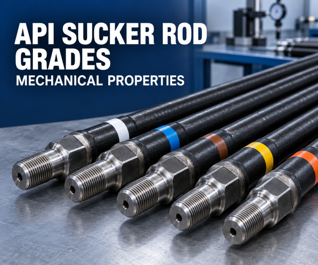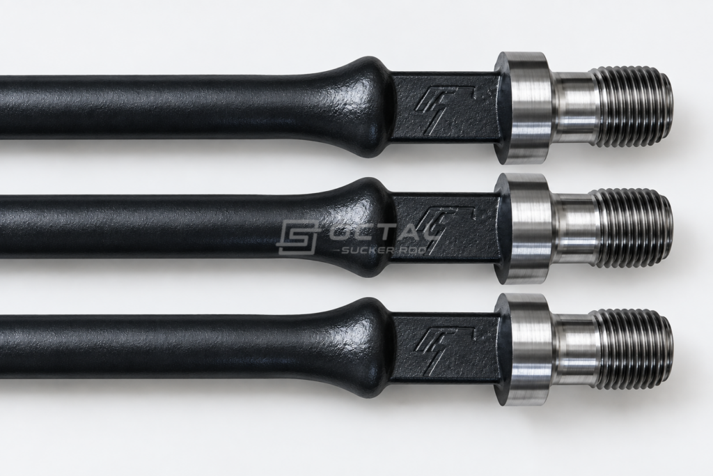
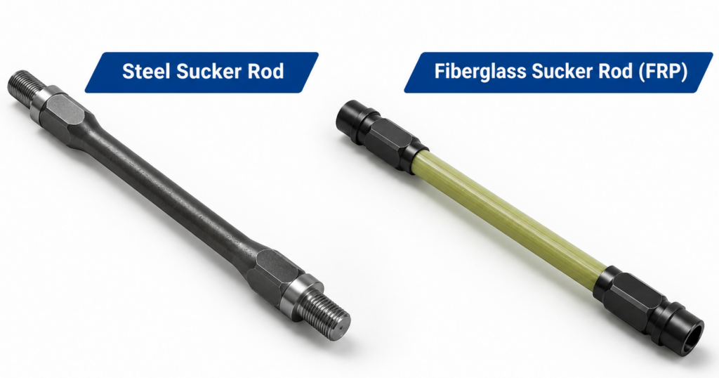
Sucker rods are essential components of rod pumping systems, connecting the surface pumping unit to the downhole pump and transmitting reciprocating motion to lift fluids from the well. The two main material types are steel sucker rods and fiberglass sucker rods, each with distinct mechanical properties and operating characteristics. Steel sucker rods are made from carbon or alloy steel, offering high axial stiffness, reliable tensile performance, and suitability for wells with demanding mechanical loads. Fiberglass sucker rods consist of glass fiber-reinforced composite bodies with metallic end fittings, providing lower weight, greater elastic elongation, and resistance to many corrosive well fluids. Steel rods are commonly selected for conventional pumping systems and applications requiring higher stiffness, while fiberglass rods may offer advantages in deep or corrosive wells where reducing rod-string weight and polished rod loads is beneficial.
Steel and Fiberglass Sucker Rod Specifications
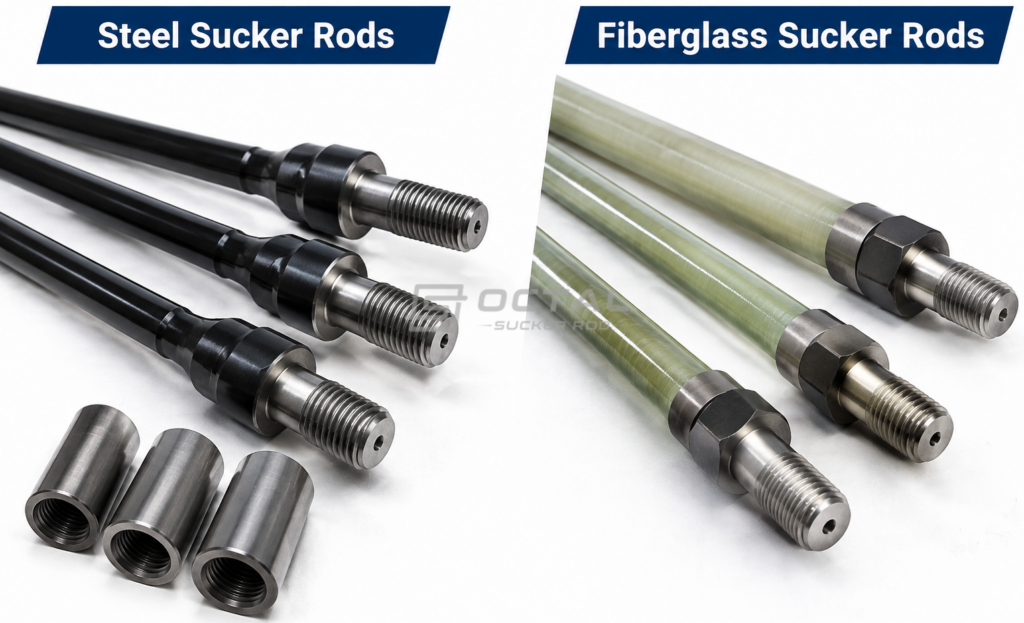
The main distinction between steel and fiberglass sucker rods lies in their sucker rod materials, material composition and mechanical behavior.Steel rods provide higher axial stiffness and established mechanical strength ranges, while fiberglass rods have lower density and greater elastic elongation under tensile loading.
Their specifications should be evaluated using different material and product requirements rather than assuming that the same acceptance criteria apply to both.
| Specification | Steel Sucker Rod | Fiberglass Sucker Rod |
| Main Material | Carbon steel or alloy steel | Glass fiber reinforced polymer |
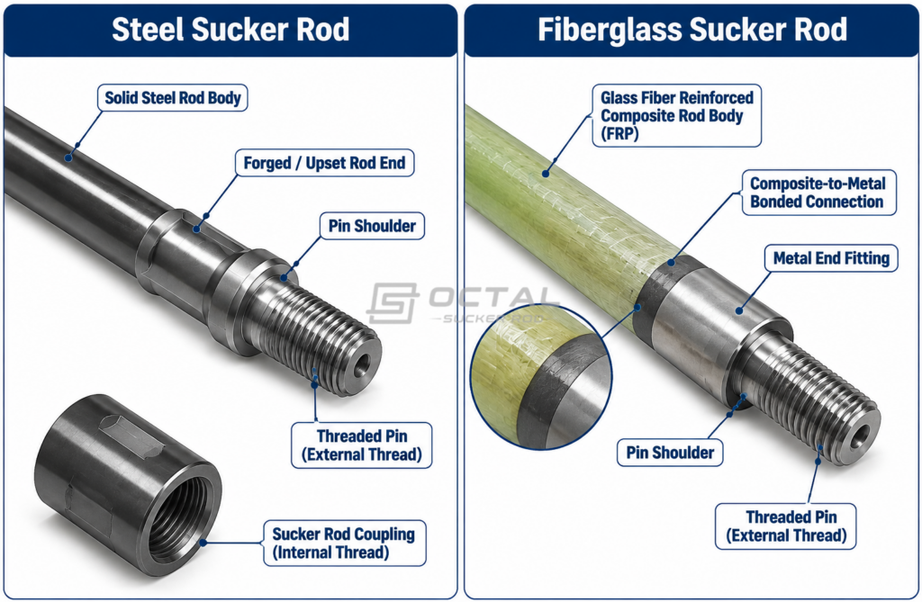
| Construction | Solid steel rod body with forged or upset ends | Composite rod body with metallic end fittings |
| Connection | Threaded pin and coupling | Manufacturer-specific end fitting and connection |
| Density | Approximately 7.85 g/cm³ | Commonly around 1.8–2.1 g/cm³, product-specific |
| Elastic Modulus | Approximately 200–210 GPa | Manufacturer-specific, generally much lower than steel |
| Axial Stiffness | High | Lower |
| Corrosion Behavior | Susceptible to corrosion depending on material and fluid conditions | Composite body resists many corrosive fluids |
| Temperature Limit | Depends on steel grade and service conditions | Limited by resin, bonding system and end fitting |
| Main Design Considerations | Strength, fatigue, corrosion and connection integrity | Tensile load, elongation, compression limitation and connection integrity |
The density and elastic modulus values above are general engineering reference ranges, not guaranteed product specifications. Fiberglass properties vary with fiber orientation, resin formulation and manufacturing process.
Mechanical Properties of Steel and Fiberglass Sucker Rods
Mechanical properties determine how a sucker rod responds to repeated tensile loading during the pumping cycle. Density affects suspended rod weight, while elastic modulus influences axial deformation and the distribution of displacement along the rod string.
Tensile Strength and Axial Stiffness
Steel sucker rods are manufactured from carbon or alloy steel and heat treated to achieve the required strength and toughness. Their high elastic modulus provides relatively low elongation under tensile loading, making steel suitable for applications requiring a stiff and mechanically stable rod string.
Fiberglass sucker rods have a lower axial elastic modulus. They can undergo greater elastic elongation under comparable loading and geometry. This behavior may increase the effective downhole plunger stroke through elastic overtravel, although the actual displacement depends on rod-string length, load variation and pumping conditions.
Elastic Elongation Comparison
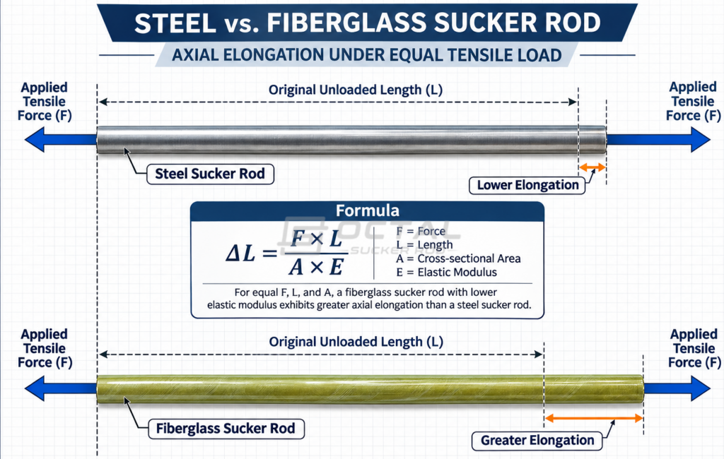
When sucker rods are subjected to tensile loads during pumping, they stretch slightly along their length. Fiberglass sucker rods generally stretch more than steel rods because their axial elastic modulus is lower. This greater elasticity can help increase the effective downhole pump stroke.
Axial elongation can be estimated using:
ΔL = FL / AE
Where:
- ΔL = Axial elongation
- F = Applied tensile force
- L = Rod length
- A = Cross-sectional area
- E = Axial elastic modulus
Steel rods stretch less, while fiberglass rods allow greater elastic elongation under the same loading conditions. This difference should be considered when calculating rod-string behavior and downhole pump displacement.
Compression Loading
Steel sucker rods can withstand compressive loads within their structural design limits, although buckling and permanent deformation remain potential risks.
Fiberglass rods require more careful compression control. Their composite structure is generally less tolerant of compressive loading, particularly around localized contact areas and metal-to-composite transitions.
For this reason, a fiberglass rod string should be designed to maintain the required tensile loading throughout the pumping cycle.
How Rod String Weight Affects Pumping Performance
Rod-string weight contributes to the load carried by the polished rod and surface pumping equipment. As pump setting depth increases, the accumulated weight of the suspended rod string becomes a more significant part of the operating load.
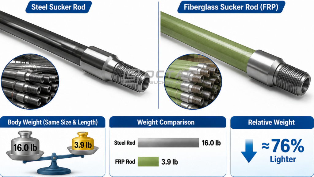
Fiberglass sucker rods offer a weight advantage because their density is substantially lower than that of steel.
For an illustrative comparison, consider two solid rods with the same 1-inch nominal body diameter and a length of 30 ft.
| Parameter | Steel Rod | Fiberglass Rod |
| Nominal Diameter | 1 in | 1 in |
| Length | 30 ft | 30 ft |
| Reference Density | 7.85 g/cm³ | 1.9 g/cm³ |
| Approximate Body Weight | 16.0 lb | 3.9 lb |
Illustrative calculation based on a solid circular body, excluding end fittings, couplings and other components. Actual fiberglass rod dimensions and weight must follow manufacturer data.
The difference becomes more significant when multiple rods are assembled into a deep rod string.
However, a lighter rod string does not automatically produce an equivalent percentage reduction in maximum polished rod load. Fluid load, pumping acceleration, friction, rod elasticity and dynamic effects also contribute to the load cycle.
A complete pumping-system analysis should consider maximum and minimum polished rod loads rather than suspended rod weight alone.
Corrosion Resistance and Temperature Limitations
Steel and fiberglass sucker rods respond differently to downhole fluid conditions.
Steel rods exposed to CO₂, H₂S, chloride-containing water and other corrosive substances may experience general corrosion, localized pitting or corrosion-assisted fatigue. The corrosion mechanism depends on fluid chemistry, temperature, pressure, material condition and corrosion-control measures.
Fiberglass composite bodies resist many corrosive environments because their polymer matrix and reinforcing fibers do not undergo conventional steel corrosion. However, this advantage does not extend automatically to metallic end fittings.
Temperature is another important consideration. Fiberglass performance depends on the resin system, fiber reinforcement and bonding materials. Elevated temperatures can affect resin properties and reduce the mechanical performance of the composite or its end connections.
| Service Condition | Steel Sucker Rod | Fiberglass Sucker Rod |
| CO₂-containing fluids | Corrosion evaluation required | Composite body generally offers better resistance |
| H₂S-containing fluids | Sour-service suitability must be verified | Resin and metallic connection compatibility require evaluation |
| Chloride-containing water | Pitting and corrosion-fatigue risks | Composite body generally resists chloride corrosion |
| High temperature | Evaluate steel grade and mechanical properties | Confirm product-specific temperature rating |
| Cyclic tensile loading | Fatigue assessment required | Composite fatigue and end-fitting performance require verification |
Neither material should be selected based on corrosion resistance alone. The complete well environment and expected mechanical loading must be considered together.
Manufacturing and Quality Control
The manufacturing processes for steel and fiberglass sucker rods are fundamentally different because their material structures and connection designs are not the same.
Steel Sucker Rod Manufacturing Process
Conventional API 11B sucker rods are produced from qualified carbon or alloy steel bars and manufactured through controlled forming, heat treatment and machining processes.The manufacturing sequence normally includes:
Steel Bar Preparation → Rod-End Upsetting → Heat Treatment → Straightening → End Machining → Thread Processing → Inspection and Protection
The upset end provides the additional material needed for the wrench section, pin shoulder and threaded connection. Heat treatment establishes the required mechanical properties, while straightening and machining control rod geometry and connection dimensions.
Important inspection items include rod-body diameter, straightness, forged-end geometry, pin dimensions, thread condition and mechanical properties.
Fiberglass Sucker Rod Manufacturing
Fiberglass sucker rods use reinforcing fibers embedded in a polymer resin matrix. The fibers provide the main tensile reinforcement, while the resin binds the structure and transfers load between the reinforcing elements.
Manufacturing commonly involves fiber impregnation, controlled composite forming or pultrusion, curing, cutting and end-fitting assembly. The exact sequence depends on the manufacturer’s process.
Quality verification should consider:
| Inspection Item | Engineering Purpose |
| Fiber and Resin System | Confirm specified material composition |
| Composite Dimensions | Verify rod-body geometry |
| Tensile Properties | Confirm allowable tensile performance |
| Resin Curing | Evaluate composite consolidation and material condition |
| End-Fitting Bond | Verify load transfer between composite body and metal fitting |
| Temperature Rating | Confirm suitability for the intended well conditions |
Fiberglass products should be evaluated against their own qualified manufacturing specifications and test procedures. API Spec 11B requirements for conventional steel sucker rods should not automatically be applied to composite products.
Common Failure Modes of Steel and Fiberglass Sucker Rods
Although both materials transmit cyclic loads, their failure mechanisms differ.
| Failure Mode | Steel Sucker Rods | Fiberglass Sucker Rods |
| Fatigue | Crack initiation at stress concentrations, forged transitions and thread roots | Matrix cracking, fiber damage and progressive composite degradation |
| Corrosion | Pitting, general corrosion and corrosion fatigue | Composite body is resistant to many fluids, but metallic fittings may corrode |
| Connection Failure | Thread wear, improper make-up and pin fatigue | End-fitting debonding or local connection failure |
| Compression Damage | Buckling or permanent deformation | Localized crushing and composite damage |
| Handling Damage | Bending, surface damage and thread damage | Impact damage, fiber damage and localized crushing |
For steel rods, the forged transition, pin shoulder and thread root are important fatigue-sensitive areas. For fiberglass rods, the transition between the composite body and metallic end fitting deserves particular attention because it transfers tensile load between two different material systems.
Inspection and handling procedures should therefore be matched to the construction of the selected rod.
Steel and Fiberglass Combination Sucker Rod Strings
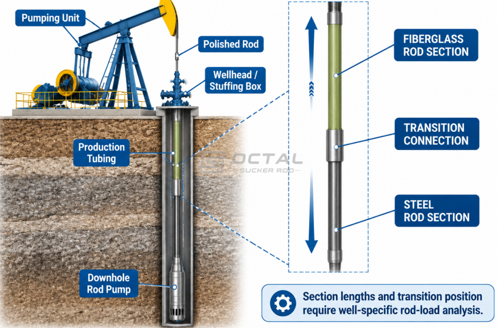
A combination sucker rod string uses both steel and fiberglass sections to balance rod-string weight, axial stiffness and tensile loading in rod-pumping systems. Fiberglass rods are generally installed in the upper section to reduce suspended weight and take advantage of greater elastic elongation, while steel rods or sinker bars may be placed below to provide additional weight and help maintain tensile loading in the fiberglass section during the pumping cycle.
The design requires careful consideration of the following parameters:
| Design Parameter | Engineering Consideration |
|---|---|
| Fiberglass Section Length | Determines the weight reduction and elastic elongation contribution |
| Steel Section Length | Influences suspended weight and load distribution |
| Transition Position | Must be established through rod-string analysis |
| Maximum Tensile Load | Must remain within the allowable working load |
| Minimum Load | Must be checked to avoid harmful compression |
| Connection Design | Must accommodate mechanical load transfer between sections |
The relative lengths and positions of steel and fiberglass sections should be calculated according to pump depth, fluid loading, pumping speed and rod-string dynamics. A fixed combination ratio cannot be applied to every well. The final design must verify tensile loading, compression risk and connection compatibility under actual operating conditions.
Why Choose Octal for Sucker Rod Supply
Octal supplies conventional steel sucker rods and related rod-string components for artificial-lift applications. Available supply configurations include different rod diameters, grades, lengths and compatible coupling arrangements.
For steel sucker rod requirements, the specification review should cover material grade, rod-body dimensions, forged-end geometry, connection configuration and inspection documentation. Material traceability, mechanical test records and dimensional inspection can support verification against the agreed purchase requirements.
When evaluating fiberglass or combination rod strings, buyers should separately confirm the composite manufacturer’s technical data, allowable working loads, temperature ratings and end-fitting specifications. Steel and fiberglass components should not be treated as interchangeable without a verified rod-string design.
FAQ
1. Can fiberglass sucker rods replace steel sucker rods completely?
Not in every application. Fiberglass rods have different tensile, elastic and compression characteristics. Complete replacement requires a new rod-string load analysis and verification of manufacturer operating limits.
2. Are fiberglass sucker rods suitable for deep oil wells?
They can be considered where reducing suspended rod weight provides an engineering benefit. Pump depth, fluid loading, temperature, tensile load and compression behavior must be evaluated.
3. Why are steel rods sometimes installed below fiberglass rods?
The steel section can help maintain tensile loading and reduce compression risk in the fiberglass section. Its length and position must be determined through rod-string calculations.
4. What is the main difference between steel and fiberglass sucker rod maintenance?
Steel rods require attention to corrosion, fatigue, thread wear and surface damage. Fiberglass rods require careful handling and inspection of the composite body, fiber damage and end-fitting integrity.