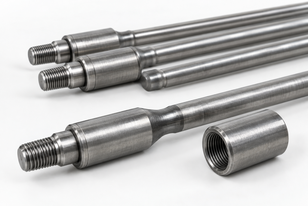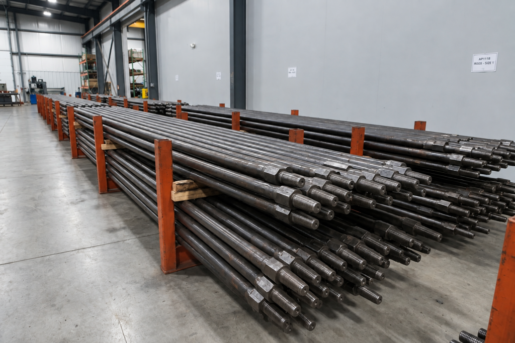
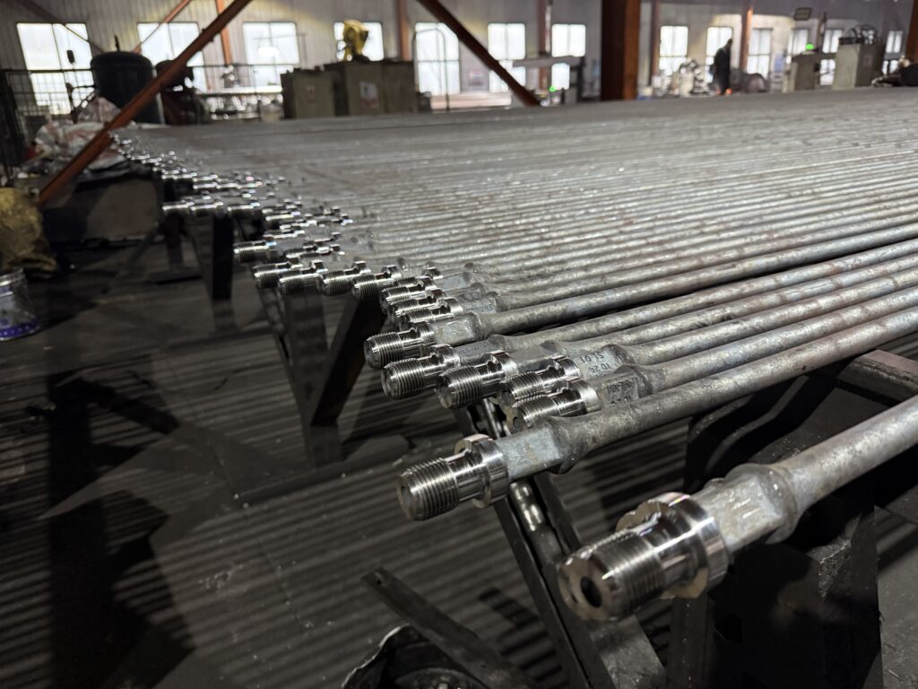
Sucker rod failure is primarily caused by fatigue cracking, corrosion, excessive tensile loading, mechanical wear, and connection damage. During rod pumping, repeated loading and unloading create cyclic stress in the rod string. Stress concentrations at pin thread roots, upset transitions, and surface defects can initiate fatigue cracks, which gradually propagate until the remaining cross-section can no longer withstand the applied load. Corrosion pits further accelerate crack initiation, while damaged threads and improper connection make-up can weaken the joints and lead to premature fracture.
Material defects, unsuitable mechanical properties, and improper rod-string design can also contribute to sucker rod failure. Identifying the actual failure mechanism requires examining fracture surfaces, material properties, operating loads, and manufacturing records. This analysis establishes the basis for selecting suitable replacement sucker rods and determining the measures needed to prevent repeated failures.
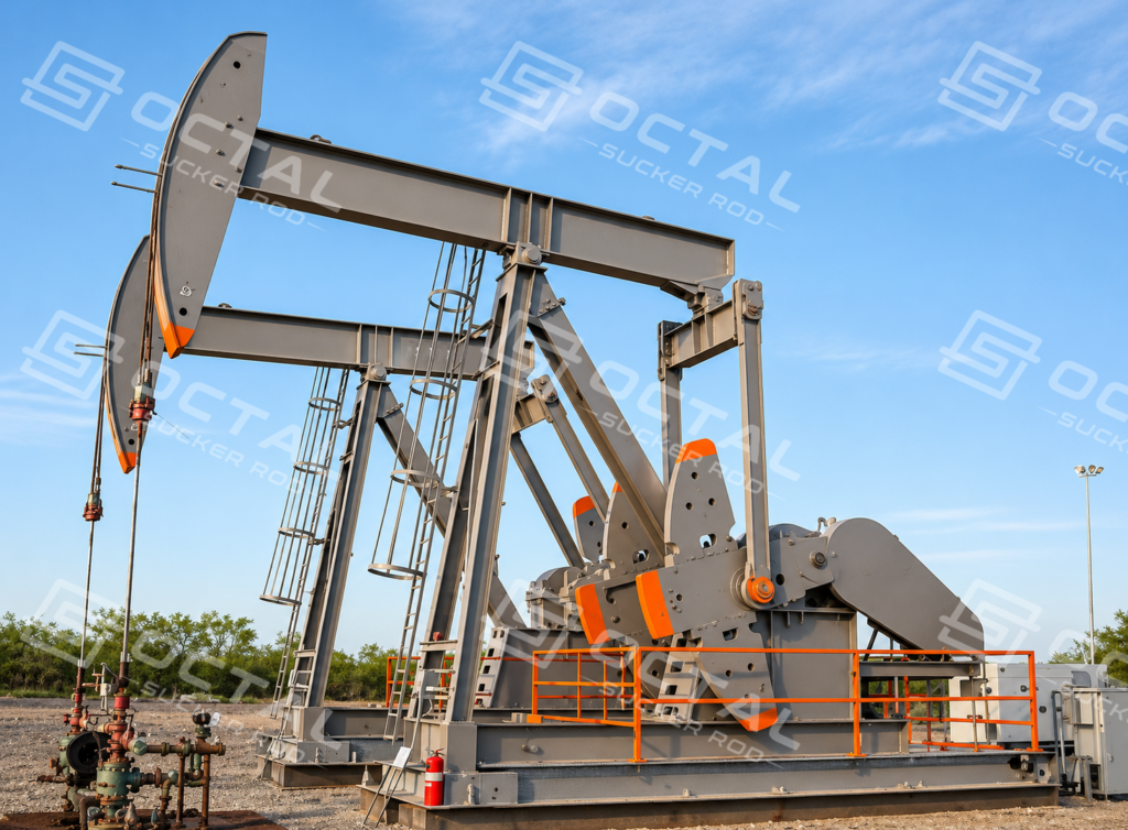
Common Causes of Sucker Rod Failure
Sucker rod failure causes generally involve cyclic fatigue, corrosion, excessive tensile loading, bending stress, mechanical damage, and connection deterioration. These factors can act independently or combine during service: surface damage or corrosion pitting can initiate a fatigue crack, while repeated pumping loads drive crack propagation until the remaining rod section can no longer sustain the applied load. Manufacturing defects and unsuitable material properties may further increase the risk of premature failure.
Fatigue and Corrosion Fatigue
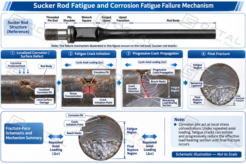
Fatigue develops under repeated loading and unloading during sucker rod pumping. Each pumping cycle changes the tensile stress carried by the rod string. Even when individual stress cycles remain below the material’s yield strength, repeated loading can initiate cracks at local stress concentrations and gradually extend them through the steel. Common crack-initiation sites include thread roots, surface scratches, corrosion pits, and geometric transitions. As a fatigue crack propagates, the effective load-bearing cross-section becomes progressively smaller until the remaining section can no longer withstand the applied load, resulting in final fracture.
Corrosion fatigue develops through the combined action of cyclic mechanical stress and a corrosive environment. Produced-water chemistry, dissolved salts, and corrosive gases can cause localized pitting on the rod surface. These pits act as stress concentrators and create potential sites for fatigue-crack initiation. Investigations of failed sucker rods have identified chloride- and CO₂-associated pitting as a contributing factor in corrosion-fatigue fractures. However, corrosion alone does not establish corrosion fatigue as the failure mechanism. The investigation must consider the relationship between localized corrosion, crack initiation, cyclic loading, and produced-fluid characteristics.
Tensile Overload
Tensile overload occurs when the applied axial load exceeds the load-bearing capacity of the affected rod section. This may result from abnormal operating conditions, excessive pulling loads, attempts to release a stuck pump, or an incorrectly designed rod string. Corrosion and mechanical wear can further reduce the effective cross-sectional area, increasing the stress carried by the remaining steel. Ductile overload may produce localized necking and plastic deformation near the fracture. However, tensile overload can also occur as the final stage of fatigue failure, when an existing crack has reduced the remaining section to the point that it can no longer sustain the applied load. Fracture-surface examination and operating-load records are therefore necessary to distinguish the two mechanisms.
Bending-Related Failure
Bending-related failure develops when transverse forces create additional bending stress in the sucker rod, alongside its normal axial loading. Bent rod bodies, wellbore deviations, dogleg sections, and rod-to-tubing contact can produce localized bending stresses. During repeated pumping cycles, these stresses combine with axial loading and accelerate fatigue-crack initiation and propagation, particularly at existing surface defects or other stress concentrations. Bending and buckling are different conditions: bending results from a bending moment, while buckling involves structural instability under axial compressive loading.
Mechanical Wear and Surface Damage
Mechanical wear develops through repeated contact between the sucker rod string and surrounding components, particularly the tubing. Abrasive contact can progressively reduce the rod-body or coupling diameter, while impact, rubbing, and improper handling may create scratches, dents, and other surface damage. These defects act as local stress concentrators under cyclic loading and can initiate fatigue cracks. Material loss and damage to protective surface layers may also expose fresh steel to produced fluids, increasing susceptibility to corrosion and accelerating fatigue-related deterioration.
Connection-Related Failure
Connection-related failure occurs when the threaded joint between sucker rods loses its mechanical integrity. The pin threads, coupling threads, and shoulder contact surfaces work together to transfer axial loads through the rod string. Improper make-up, cross-threading, inadequate lubrication, contaminated threads, or incompatible components can compromise thread engagement and connection performance.
When the intended shoulder contact is not maintained, additional bending stress may develop in the pin during cyclic operation, promoting fatigue cracking near the thread root or undercut region. Coupling wear, impact damage, and deteriorated mating surfaces can further weaken the joint. Failure analysis should therefore examine both the pin and coupling, together with their thread condition and make-up history.
Material and Manufacturing Defects
Material and manufacturing defects can introduce discontinuities that weaken the sucker rod or create potential crack-initiation sites. These may include non-metallic inclusions, longitudinal seams, forging cracks, laps, folds, and machining damage. Defects in the raw steel, forging process, or upset transition can create local stress concentrations, while unsuitable heat-treatment conditions may result in inconsistent microstructure, hardness, or mechanical properties.
Such defects should not automatically be classified as the root cause of failure. Their significance must be established by examining the actual crack origin, metallographic structure, mechanical test results, and available manufacturing records. This helps distinguish manufacturing-related damage from fatigue, corrosion, and mechanical deterioration developed during service.
Common Sucker Rod Failure Locations
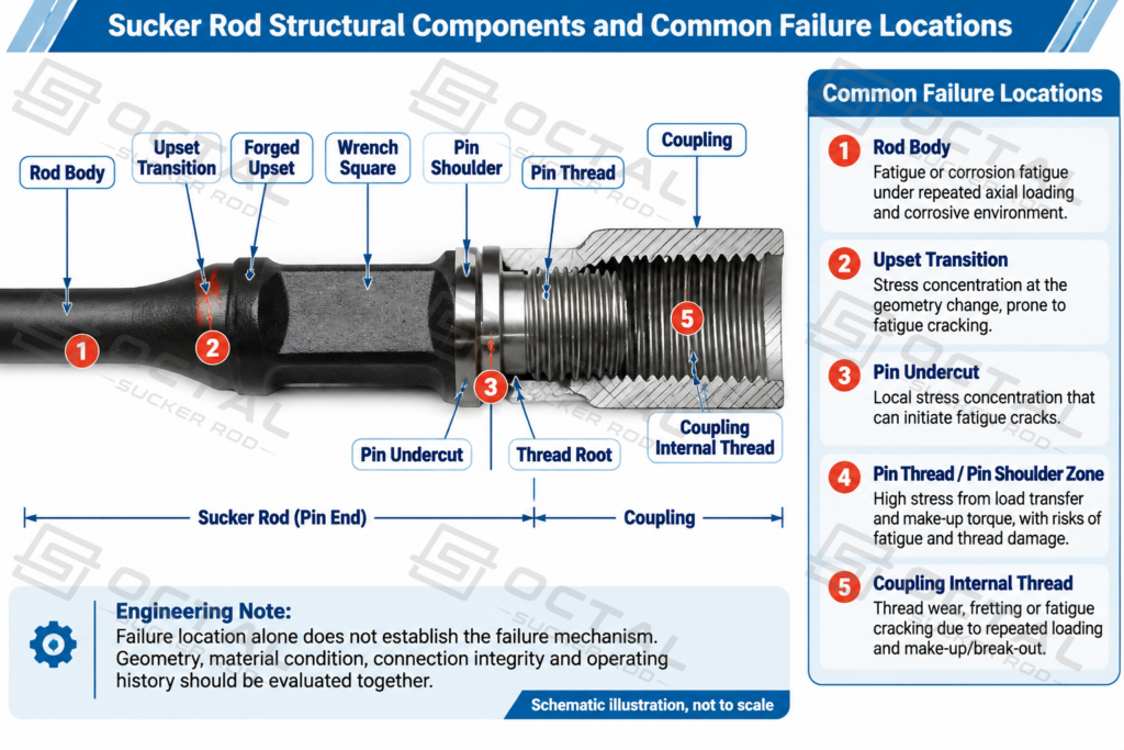
Sucker rod failures occur at several structural locations, depending on local stress distribution, connection geometry, material condition, and operating loads. The main locations include the rod body, forged upset transition, pin undercut, thread roots, and coupling. Each area has distinct structural characteristics that influence how cracks initiate, propagate, and eventually lead to component failure.
| Failure Location | Typical Fracture or Damage Characteristics |
|---|---|
| Rod Body | Transverse fatigue fractures, corrosion-fatigue cracks, surface pitting, abrasive wear and bending-related damage |
| Forged Upset and Transition Zone | Localized cracking, forging laps, folds, surface discontinuities and fractures near the cross-sectional transition |
| Pin Undercut and Thread Root | Fatigue cracks around the undercut, thread-root fractures and pin separation under cyclic loading |
| Pin Shoulder and Wrench Square | Shoulder-face deformation, contact damage, impact marks and wrench-square wear affecting connection integrity |
| Coupling Thread Root and Body | Internal-thread cracking, coupling-body fractures, external abrasion, corrosion and localized wall thinning |
The rod body and forged transition are associated with damage in the main rod section, while pin and coupling failures involve the threaded connection and its load-transfer surfaces. These locations have different fracture characteristics, and multiple forms of damage may develop within the same connection or rod section.
How to Identify the Root Cause of Sucker Rod Failure
Identifying the root cause of sucker rod failure requires correlating fracture characteristics with operating conditions, material properties, and manufacturing records. The fracture location and visible damage help narrow down possible failure mechanisms, while laboratory results and well-operation data establish whether fatigue, corrosion, overload, connection damage, or manufacturing defects contributed to the failure.
| Evidence Examined | Key Information | Diagnostic Purpose |
|---|---|---|
| Operating and rod-string records | Rod grade, diameter, string position, pumping speed, stroke length, polished-rod loads, and well conditions | Identify abnormal loading, unsuitable rod-string configuration, and recurring operating problems |
| Fracture-surface examination | Crack origin, fatigue propagation regions, final rupture area, deformation, and corrosion features | Distinguish fatigue, corrosion-assisted cracking, and tensile overload |
| Material and metallurgical testing | Chemical composition, hardness, tensile properties, microstructure, and material discontinuities | Determine whether material properties, heat treatment, or manufacturing defects contributed to failure |
| Connection and manufacturing records | Pin and coupling dimensions, thread condition, shoulder contact, make-up records, and production traceability | Identify connection-related problems and assess possible manufacturing contributions |
The root cause should be established by matching the fracture origin and damage progression with the actual operating history and material condition. A fatigue fracture may involve corrosion pitting, while a pin failure may involve both thread damage and an unsuitable make-up condition. The final failure report should distinguish the primary failure mechanism from contributing factors and document the evidence supporting each conclusion.
Selecting Replacement Sucker Rods After a Failure
Selecting replacement sucker rods requires more than matching the diameter and grade of the failed rod. The replacement specification should reflect the confirmed failure mechanism, actual rod-string loading, connection requirements, and downhole operating conditions. Replacing a broken rod without addressing the original cause may result in repeated failures, even when the replacement has a higher nominal tensile strength.
The main engineering factors should be evaluated before confirming the replacement specification.
| Selection Factor | Engineering Assessment | Replacement Requirements |
|---|---|---|
| Previous failure mechanism | Determine whether the failure involved fatigue, corrosion, tensile overload, bending, mechanical wear, or connection damage | Address the identified failure mechanism rather than simply reproducing the original configuration |
| Rod grade and load capacity | Review polished-rod loads, rod-string weight, pump load, stroke length, pumping speed, and dynamic loading | Select a grade with sufficient mechanical strength for the calculated operating loads |
| Rod diameter and length | Evaluate cross-sectional area, rod-string configuration, standard rod lengths, and available tubing clearance | Confirm dimensions and maintain compatibility with the existing rod string |
| Connection and coupling | Verify pin dimensions, thread designation, shoulder geometry, coupling type, and connection compatibility | Ensure the replacement components form a mechanically compatible connection |
| Downhole operating environment | Review produced-water chemistry, chloride concentration, CO₂, H₂S, pH, temperature, and corrosion-control practices | Select suitable material and establish appropriate corrosion-control measures |
| Inspection and documentation | Define material verification, mechanical testing, dimensional inspection, thread inspection, and traceability requirements | Specify applicable inspection methods, acceptance criteria, and documentation before ordering |
Rod grade selection should be based on the load carried by each section of the rod string rather than well depth alone. In a tapered rod string, different sections carry different axial loads and may require different diameters or grades. High-strength sucker rods can increase tensile load capacity within a given diameter, but higher strength does not automatically improve corrosion resistance or eliminate fatigue damage. Material properties, heat-treatment condition, cyclic loading, and service environment must be considered together.
Connection compatibility also requires attention when replacement rods are combined with existing components. Matching the rod-body diameter does not guarantee that the pin and coupling are interchangeable. Thread form, shoulder geometry, connection dimensions, and applicable product specifications must be verified before installation.
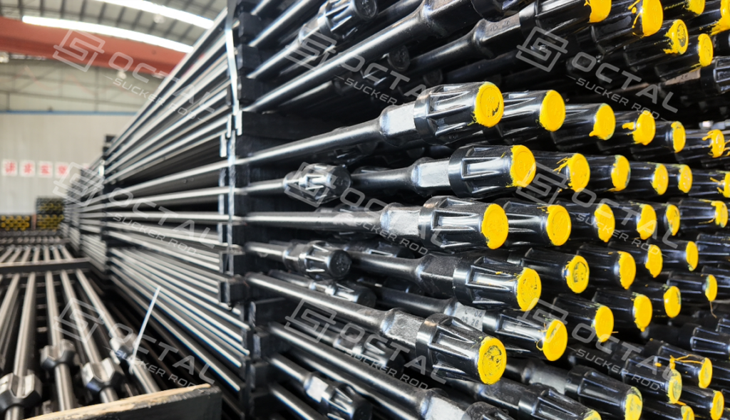
How to Prevent Sucker Rod Failure
Preventing repeated sucker rod failures requires corrective measures based on the identified failure mechanism. The main priorities are controlling rod-string loading, managing corrosion, reducing mechanical contact, maintaining connection integrity, and preventing damage during handling and installation.
| Prevention Area | Recommended Measures | Key Control Points |
|---|---|---|
| Rod-String Design and Operating Loads | Verify rod grade, diameter, taper configuration, and load distribution against actual pumping conditions. Reassess the design when operating parameters change. | Polished-rod loads, pump load, stroke length, pumping speed, and dynamometer records |
| Corrosion Management | Monitor produced-fluid chemistry and maintain a suitable corrosion-inhibitor program. Evaluate material compatibility with the well environment. | Water chemistry, chloride concentration, CO₂, H₂S, temperature, and inhibitor performance |
| Rod-to-Tubing Contact | Evaluate well deviation, dogleg severity, and tubing clearance. Select and position rod guides according to actual well geometry and wear conditions. | Rod-body wear patterns, tubing condition, and rod-guide placement |
| Connection Integrity | Maintain clean and undamaged threads, use suitable thread lubricant, and follow the specified connection make-up procedure. | Pin and coupling threads, shoulder contact, make-up condition, and connection records |
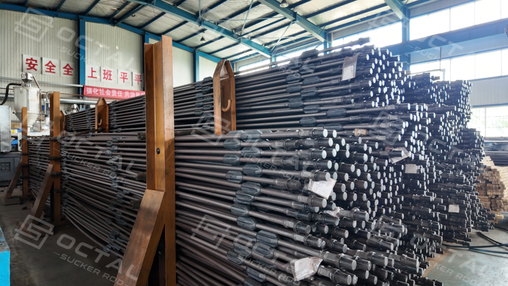
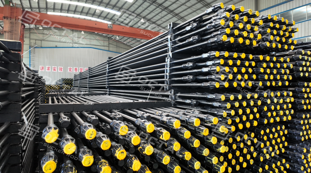
| Handling, Storage, and Reuse | Use suitable lifting equipment, protective storage racks, separators, and thread protectors. Inspect recovered rods against applicable acceptance criteria before reuse. | Surface damage, bending, thread condition, and dimensional inspection |
Failure records should also be maintained to identify recurring problems across wells and operating periods. Recording the failure depth, rod position, grade, connection type, confirmed failure mechanism, and corrective action helps determine whether previous measures have effectively reduced repeat failures.
FAQ
Q: What are the most common causes of sucker rod failure?
A: Common causes include fatigue, corrosion fatigue, tensile overload, bending stress, rod-to-tubing wear, connection damage, and manufacturing defects. These mechanisms can interact, with corrosion pits, thread roots, and surface discontinuities creating stress concentrations that accelerate fatigue cracking under cyclic pumping loads.
Q: Can a sucker rod fail below its yield strength?
A: Yes. Repeated pumping cycles can initiate and propagate fatigue cracks even when nominal operating stress remains below the material’s yield strength. Local stress concentrations at corrosion pits, thread roots, bends, or surface defects can accelerate crack growth until the remaining cross-section cannot sustain the applied load.
Q: How can fatigue failure be identified on a sucker rod fracture surface?
A: A fatigue fracture may show three distinct regions: crack initiation, progressive crack propagation, and final rupture. Beach marks and ratchet marks can help identify the crack origin and propagation direction, although their visibility depends on fracture conditions and surface preservation.
Q: Why do sucker rod connections fail at the pin or coupling?
A: Connection failures can develop when insufficient make-up preload allows the pin and coupling shoulder faces to separate under cyclic loading. This adds bending stress to the pin and can initiate fatigue cracking at the first fully formed thread root above the undercut. Damaged threads, improper make-up, excessive torque, and coupling deterioration can also contribute to connection failure.