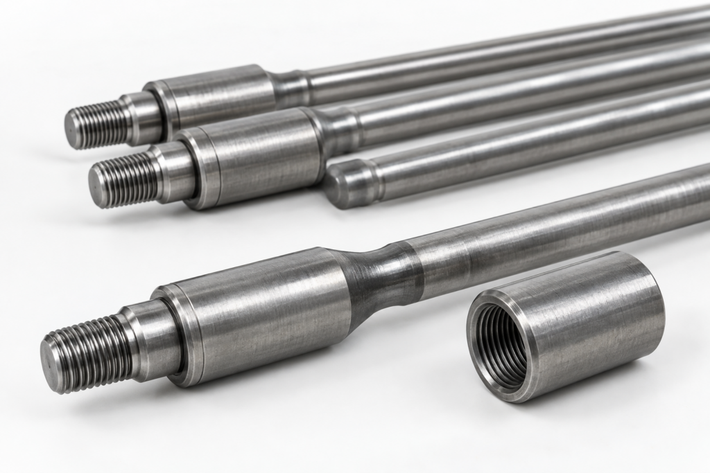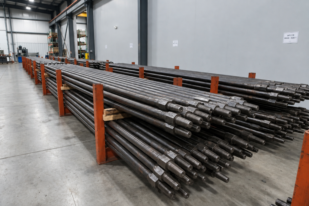
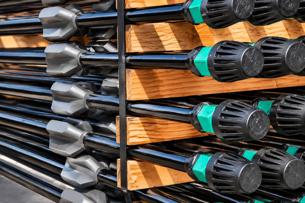
Uniform sucker rod strings and tapered sucker rod strings are two configurations used in reciprocating rod-lift systems to transmit mechanical loads from the surface pumping unit to the downhole pump. A uniform sucker rod string consists of sucker rods with the same nominal body diameter throughout its length, while a tapered sucker rod string combines two or more rod diameters in separate sections. Both configurations are assembled using threaded sucker rods and compatible couplings, but differ in how rod diameter and cross-sectional area are distributed along the string.
In a uniform configuration, one rod diameter must accommodate the loading requirements of the entire string. A tapered configuration uses larger-diameter rods in the upper sections and smaller-diameter rods in the lower sections, matching the changing tensile load along the string. This arrangement can reduce unnecessary suspended rod weight while maintaining the required load capacity, provided that each section is properly designed.
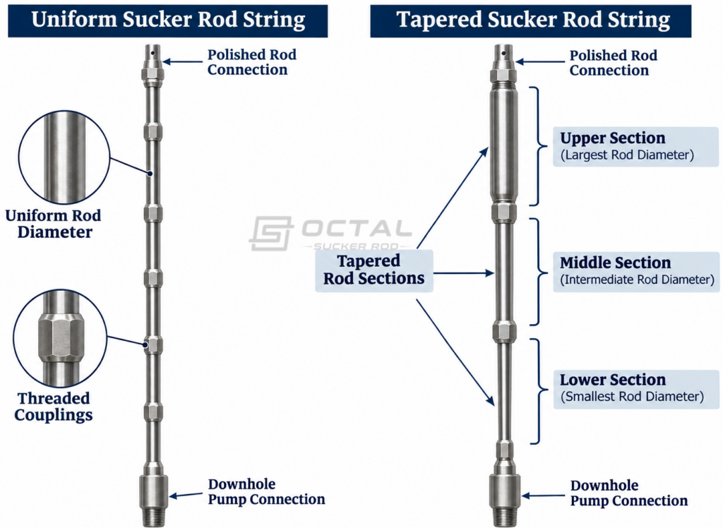
Selecting between uniform and tapered sucker rod strings requires evaluating pump setting depth, rod string weight, dynamic loads, material grade, fatigue resistance and well conditions. This article examines their structural differences, load distribution, rod diameter selection and design requirements to explain how each configuration performs and which conditions favor its use.
Uniform Sucker Rod String Design
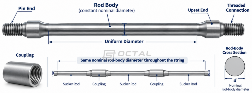
A uniform sucker rod string consists of conventional sucker rods with the same nominal rod-body diameter throughout the string. The individual rods are connected by threaded couplings to form a continuous mechanical load path between the polished rod and the downhole pump.
For example, a string assembled entirely from 7/8-inch sucker rods retains the same nominal rod-body diameter along its length. The actual assembly still contains threaded connections and couplings, but no change in nominal rod size is introduced between sections.
Structural Characteristics
The main characteristic of a uniform rod string is its consistent rod-body cross-sectional area. This simplifies rod inventory, string assembly and the identification of replacement components during workover operations.
However, a constant rod diameter does not mean that the tensile stress remains constant throughout the string.
The upper sections support the weight of the rods below them, while the lower sections carry a smaller accumulated rod weight. Additional loads associated with the pumping cycle also affect the instantaneous force at different positions along the string.
Consequently, the upper and lower sections can experience different stress levels even when their nominal diameters and material grades are identical.
Advantages and Engineering Limitations
A uniform sucker rod string offers several practical advantages:
- Simplified configuration: One nominal rod diameter reduces the number of rod sizes required for string assembly.
- Straightforward inventory management: Replacement rods and couplings can be managed around a more consistent size specification.
- Fewer diameter transitions: The string does not require changes between different rod-body diameters.
- Simpler initial selection: A single rod size can be evaluated against the calculated operating loads and applicable design criteria.
Its main limitation is that one rod diameter must satisfy the loading requirements throughout the entire string. If the selected diameter is governed by the higher tensile load near the surface, the lower sections may contain more cross-sectional capacity than their local loading requires.
This can increase the total suspended rod weight and the load that the surface pumping equipment must handle.
Uniform configurations therefore remain a practical option where the calculated load profile, pump depth, rod size availability and operating conditions permit a single diameter to meet the required design criteria.
Tapered Sucker Rod String Design
A tapered sucker rod string uses two or more nominal rod diameters arranged in separate sections. The diameter generally increases toward the surface because the upper portions must support the accumulated weight of the rod sections below them.
This arrangement approximates the mechanical principle of a continuously tapered rod, but uses commercially available rod sizes and conventional threaded connections.
How a Tapered Rod String Is Configured
A conventional tapered string may contain three sections with different nominal diameters.
For illustration, a hypothetical configuration could use:
| Rod section | Nominal rod diameter | Position |
| Upper section | 1 in | Near the surface |
| Middle section | 7/8 in | Intermediate depth |
| Lower section | 3/4 in | Near the downhole pump |
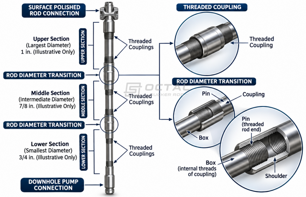
Illustrative configuration only. These dimensions are not a recommended design for a particular well.
The larger upper rods provide greater cross-sectional area to carry the accumulated tensile load. Smaller rods are used in lower sections where the accumulated weight of the suspended rod string is generally lower.
The exact number of sections, rod diameters and section lengths must be established through engineering calculations. A three-section arrangement is not universally suitable for every well.
Why Are Larger Rods Used Near the Surface?
The reason comes from the distribution of rod weight along the string.Consider a simplified static condition. At any point in a vertically suspended rod string, the axial force includes the weight of the rods hanging below that point.As the calculation moves upward, more rod sections contribute to the accumulated load. The upper sections therefore generally carry higher tensile forces than the lower sections.
For a simplified rod-body calculation:
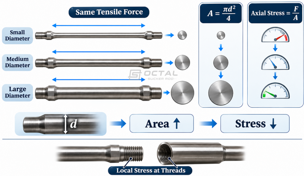
Axial Stress = Axial Tensile Force / Cross-Sectional Area
Where:
- Axial Stress (σ): Nominal axial stress
- Axial Tensile Force (F): Applied tensile force
- Cross-Sectional Area (A): Rod-body cross-sectional area
For a solid circular rod:
Cross-Sectional Area (A) = π × d² / 4
Where:
- π = 3.1416
- d = Nominal rod-body diameter
Where d is the nominal rod-body diameter.
Increasing the diameter increases the cross-sectional area and can reduce nominal axial stress under a given tensile force.
However, actual sucker rod loading is dynamic. The design must also account for fluid load, acceleration, elastic behavior, friction and cyclic loading. Static rod weight alone cannot establish the final rod diameter or taper length.
Advantages and Design Considerations
A tapered sucker rod string allows different rod diameters to be assigned according to the load requirements of each section.
| Design Aspect | Engineering Benefit or Consideration |
| Load Distribution | Matches rod diameter to the calculated tensile load along the string. |
| String Weight | Smaller lower-section rods can reduce total suspended weight. |
| Rod Selection | Allows different diameters and material grades to be combined. |
| Section Transitions | Requires compatible couplings, properly calculated section lengths and adequate tubing clearance. |
The final configuration must be verified for tensile stress, fatigue performance and connection compatibility throughout the string.
Uniform vs Tapered Sucker Rod String Comparison
Although both configurations transmit reciprocating mechanical loads to the downhole pump, their structural arrangements produce different design considerations.
| Comparison item | Uniform Rod String | Tapered Rod String |
| Rod diameter | One nominal diameter | Multiple nominal diameters |
| String arrangement | Single-size configuration | Multiple sections |
| Cross-sectional area | Constant along rod bodies | Changes between sections |
| Load distribution | Varies with position | Accommodated through sectional sizing |
| Suspended weight | Depends on selected diameter and total length | Can be optimized through diameter combinations |
| Rod inventory | Fewer size variations | Multiple sizes required |
| Coupling arrangement | More uniform | Requires compatible size transitions |
| Design procedure | Relatively straightforward | Requires sectional calculations |
| Replacement planning | Simpler size identification | Section-specific identification |
| Design objective | Meet the load requirements with one diameter | Match rod capacity to the changing load profile |
Which Configuration Provides Better Load Utilization?
The main distinction is how the available rod-body cross-sectional area is distributed along the string.
A uniform string uses the same nominal diameter even though the axial force generally changes with depth. A tapered string allows the designer to adjust the diameter between sections to better match the calculated loading conditions.
This does not mean a tapered string automatically provides better performance in every well.
If the selected rod diameters or section lengths are inappropriate, a tapered configuration can introduce localized stress problems or unnecessary connection transitions. A properly selected uniform string may be more practical when one rod size satisfies all applicable loading and fatigue requirements.
The comparison must therefore be based on the calculated performance of the complete string rather than the number of rod diameters used.
Sucker Rod String Load Distribution and Stress Analysis
Load distribution is the engineering basis for deciding whether a uniform or tapered arrangement is appropriate.
During reciprocating pumping, the rod string experiences changing tensile forces throughout the pumping cycle. The magnitude and distribution of these forces depend on the pumping system and the operating conditions.
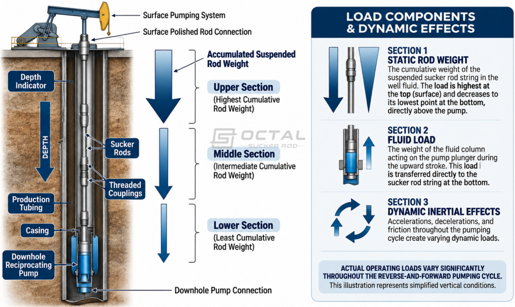
Static Rod Weight
The self-weight of the suspended rod string creates an axial tensile force.
For a vertical well under simplified static conditions, the force at a particular section is related to the weight of the rod sections below that point.
The upper sections carry a greater accumulated rod weight because they support more of the suspended string.
In a deviated well, this relationship becomes more complex. The axial component of rod weight and contact forces against the tubing must be considered, rather than applying a purely vertical hanging-string calculation.
Dynamic and Fluid Loads
During operation, the rod string accelerates and decelerates as the pumping unit completes its reciprocating cycle.The downhole pump also experiences fluid loading associated with the pressure differential across the pump plunger.
Other factors affecting rod loads include:
- Pump setting depth and fluid level.
- Pumping speed and stroke length.
- Rod string elasticity.
- Fluid characteristics and gas interference.
- Mechanical friction and well inclination.
- Surface unit geometry and counterbalance conditions.
These factors influence the maximum and minimum axial loads experienced by different sections of the string.A design based solely on static rod weight may therefore underestimate the actual operating stresses.
Axial Stress in Different Rod Sections
Axial stress varies along a sucker rod string because the tensile load and rod diameter differ between sections. In a tapered configuration, each section must be evaluated separately using its calculated axial load and rod-body cross-sectional area.
The upper sections generally carry higher accumulated tensile loads, while smaller-diameter lower sections carry less suspended rod weight. Rod diameter selection must therefore account for maximum tensile stress, allowable material strength and cyclic loading during pumping operations.
Fatigue performance should also be checked at each section, particularly around threaded connections where stress concentrations may contribute to premature failure.
How to Determine Sucker Rod Diameters and Taper Lengths
Selecting sucker rod diameters and taper lengths requires evaluating the actual load profile along the rod string rather than relying on well depth alone. The design process involves well and pumping conditions, static and dynamic load calculations, rod material properties, fatigue limits and the mechanical compatibility of each section.
Step 1: Establish Well and Pumping Conditions
The initial design should be based on the following operating data:
| Design Parameter | Information Required |
| Pump setting depth | Installed pump depth and rod string length |
| Well trajectory | Measured depth, vertical depth and inclination profile |
| Pumping conditions | Stroke length, pumping speed and pumping unit type |
| Fluid loading | Pump displacement, fluid level and operating pressure |
| Tubing dimensions | Tubing internal diameter and dimensional restrictions |
| Produced fluids | Fluid properties, CO₂, H₂S and other corrosive components |
These inputs establish the boundary conditions for rod string calculations. In deviated wells, the inclination profile is particularly important because rod-tubing contact and friction can affect the actual axial load and wear distribution.
Step 2: Calculate Rod String Loads
Calculate the static and dynamic loads acting on different sections of the rod string. Static loading includes the suspended weight of the rods, while dynamic loading accounts for reciprocating acceleration, fluid load and mechanical effects during the pumping cycle. Maximum and minimum rod loads should be evaluated at relevant positions along the string to establish the tensile stress range and identify the sections with the highest mechanical demands.
Step 3: Select Rod Diameters and Material Grades
Rod diameters should be selected according to the calculated axial loads and allowable stress of the selected material. For each section, the nominal rod-body stress can be evaluated using the axial force divided by its cross-sectional area. Material grade selection must also consider yield strength, tensile properties, fatigue resistance, heat-treatment condition and corrosion exposure. The rod-body capacity and threaded connection strength should be checked separately.
Step 4: Determine Taper Section Lengths
The length of each diameter section should be established from the calculated load distribution and applicable fatigue design criteria. Larger-diameter rods are generally positioned in the upper sections to accommodate accumulated tensile loads, while smaller diameters may be used in lower sections where the calculated loading permits. The transition points must be verified against the selected design method rather than determined by arbitrary divisions of total rod string length.
Step 5: Verify the Complete Rod String
Before finalizing the configuration, verify the maximum and minimum tensile loads, fatigue performance, coupling compatibility and tubing clearance for the complete assembly. The total suspended rod weight must also remain within the operating capacity of the pumping system. The final rod tally should identify the diameter, material grade, section length and connection type of each section, providing a clear basis for procurement, assembly and inspection.
Engineering Factors That Affect Rod String Selection
The choice between uniform and tapered configurations is influenced by several operating conditions.
Pump Setting Depth and Rod Load
Deeper pump settings generally increase the suspended rod weight and may increase the need for sectional rod sizing.
However, pump depth alone does not determine whether a tapered string is required. The calculated maximum and minimum loads, selected rod grade and pumping conditions must be evaluated together.
Well Inclination and Rod-Tubing Contact
In deviated wells, the rod string can contact the tubing during reciprocating movement.
This introduces friction and side loading that are not adequately represented by a simple vertical-string calculation.
The contact forces can accelerate rod and tubing wear, particularly around coupling locations. Rod guides and other appropriate wear-control measures may be considered where the well geometry and operating conditions justify their use.
Rod Grade and Fatigue Resistance
The selected sucker rod grade determines its mechanical strength and allowable operating stress under cyclic loading. Different grades offer different tensile properties and fatigue performance, making grade selection an important part of tapered and uniform rod string design.
When selecting rod grades, engineers should consider maximum rod loads, stress range, corrosion exposure and operating conditions. Rod diameter and material grade must be evaluated together to ensure that each section meets the required strength and fatigue design criteria.
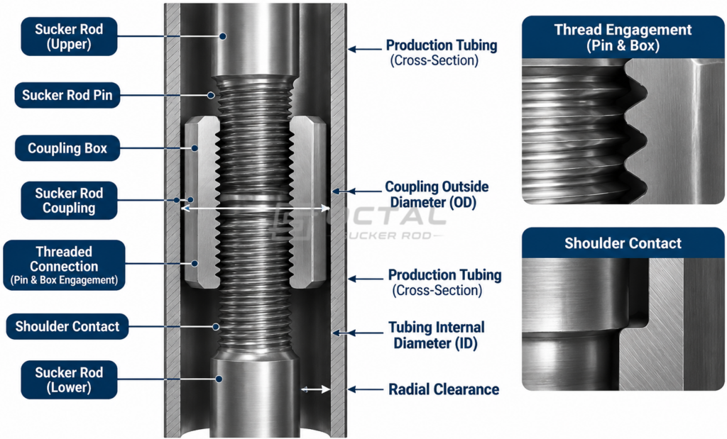
Coupling Compatibility and Tubing Clearance
A tapered string introduces changes in rod size between sections.
Each transition must use compatible threaded connections and couplings. The coupling outside diameter must also be checked against the available tubing internal diameter.
Insufficient clearance can increase the risk of mechanical interference, particularly in deviated sections where rod-tubing contact already exists.
The complete assembly should therefore be checked against the tubing configuration rather than selecting rod sizes solely from their tensile capacity.
When to Use Uniform or Tapered Sucker Rod Strings
Neither configuration is universally superior. The appropriate arrangement depends on the calculated loads, well conditions, available rod sizes and operational requirements.
| Operating or design condition | Configuration to evaluate |
| One rod diameter satisfies all load and fatigue requirements | Uniform Rod String |
| Rod loading changes significantly along the string | Tapered Rod String |
| Suspended rod weight is a major design consideration | Tapered Rod String |
| Simple inventory and replacement requirements are preferred | Uniform Rod String |
| Different rod sections require different cross-sectional capacities | Tapered Rod String |
| Diameter transitions create unacceptable clearance or connection constraints | Reassess the Tapered Design |
Uniform Rod String Selection
A uniform string is appropriate when a single rod diameter and grade can satisfy the maximum operating load, fatigue requirements and connection limitations throughout the complete string.
It can simplify procurement and workover planning by reducing the number of rod sizes required.
Tapered Rod String Selection
A tapered string should be evaluated when a single diameter does not provide an efficient arrangement for the calculated load profile.
By using larger rods in more heavily loaded upper sections and smaller rods in lower sections where permitted by the design, the configuration can improve the distribution of rod-body capacity along the string.
The final choice should be verified through an appropriate design procedure that considers dynamic loading, fatigue, well trajectory and connection requirements.
Conclusion and Sucker Rod Supply Support from Octal
Selecting between uniform and tapered sucker rod strings requires evaluating rod diameter, load distribution, material grade, fatigue resistance and well conditions. Uniform strings offer simpler assembly, while tapered strings allow different rod diameters to match the changing loads along the string. The final configuration should also account for coupling compatibility and tubing clearance.
Octal supplies API 11B sucker rods and related components, including pony rods, polished rods, sinker bars and couplings. We support different rod diameters, material grades, lengths and connection configurations for both uniform and tapered rod string requirements.
Our supply services include specification review, manufacturing coordination, heat-treatment control, mechanical testing, dimensional inspection and thread gauging. Material certificates, inspection records and heat/lot traceability documents can be provided according to applicable standards and purchase requirements. Products can also be identified and packaged by size and grade to support receiving inspection and field assembly.
For a suitable supply proposal, customers can provide their required rod diameters, grades, section lengths, coupling specifications and well operating conditions for Octal’s review.
FAQ
Q1. What is the main difference between a uniform and a tapered sucker rod string?
A1:A uniform string uses one nominal rod-body diameter throughout its length, while a tapered string combines different rod diameters in separate sections to accommodate changing load requirements.
Q2.:Why are larger sucker rods generally installed in the upper sections of a tapered string?
A2:Upper sections support the accumulated weight of the rods below them and generally experience higher axial tensile loads. Larger cross-sectional areas can provide the required tensile capacity at these locations.
Q3.:Does a tapered sucker rod string always reduce pumping unit load?
Not automatically. A properly designed tapered configuration can reduce unnecessary suspended rod weight compared with an appropriately evaluated uniform alternative, but the actual effect depends on rod dimensions, material grades, pump loading and dynamic operating conditions.
Q4.:How are tapered sucker rod section lengths determined?
Section lengths are calculated using the selected rod string design procedure and the load and fatigue requirements along the string. They should not be assigned using a fixed percentage of total well depth without engineering verification.