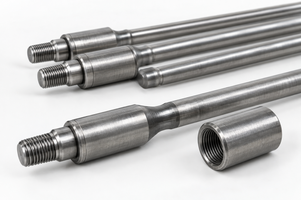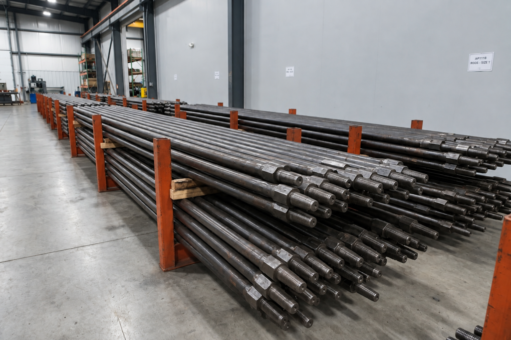
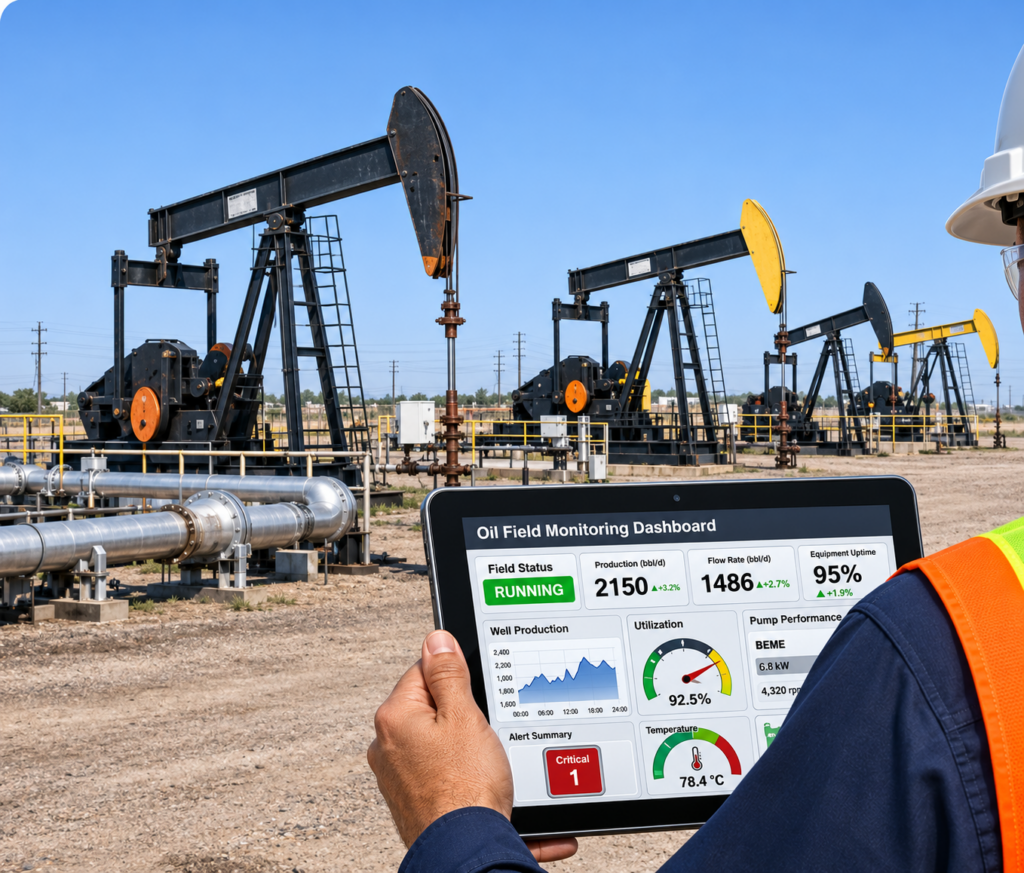
IoT in Oil and Gas applications focus on collecting and analyzing operating data from oil and gas wells and artificial lift equipment, helping operators understand production conditions across multiple well sites. At beam pumping wells, dynamometer systems acquire polished rod load and displacement data to generate surface dynamometer cards for analyzing pumping performance. Acoustic liquid level testers use pulse generation and reflected signal analysis to determine well fluid levels. For progressive cavity pumps (PCPs), monitoring can use available equipment and control-system data to review operating conditions. RFID identification serves a separate role by linking selected production components, such as sucker rods, tubing, and pumping equipment, with their technical and service records.
These applications connect field measurements, equipment operating information, and well records through data acquisition terminals, communication networks, and centralized management software. Operators can remotely review measurement results, compare operating conditions between wells, track equipment usage, and access maintenance histories without relying entirely on individual field inspection records. The collected information provides a practical basis for production monitoring, equipment assessment, and maintenance planning, helping improve oilfield production accuracy and reduce overall operating costs.
How Does IoT Collect and Transmit Oilfield Production Data?
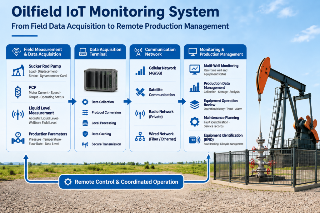
IoT Applications in Oilfield Production generally involve four connected stages: field data acquisition, signal processing, data transmission, and centralized information management.
The process begins with measurement instruments installed or connected to oilfield production equipment. These instruments collect physical measurements and operating signals, which are received and processed by data acquisition terminals. The processed information is then transmitted through wired or wireless communication networks to a centralized monitoring platform, where it is organized into operating records, measurement trends, and equipment management data for remote review.
Main Components of an Oilfield IoT Monitoring System
A typical oilfield IoT monitoring system consists of several interconnected components. Each component performs a specific task in acquiring, processing, transmitting, or managing production information.
| System Component | Main Function | Typical Application |
|---|---|---|
| Field Measurement Instruments | Acquire physical measurements and operating signals | Dynamometer, acoustic liquid level tester |
| Equipment Identification Devices | Identify individual production components | RFID chips and protective assemblies |
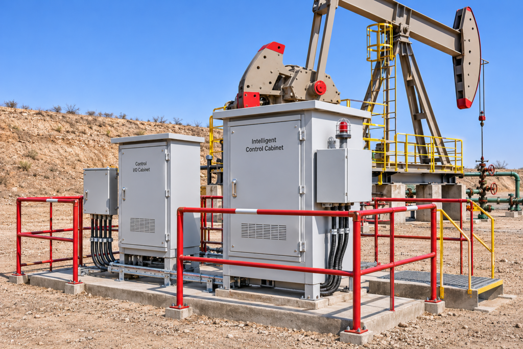
| Data Acquisition Terminals | Receive, process, and organize measurement signals | Dynamometer card acquisition host, intelligent control terminal |
| Communication Equipment | Transfer field information to the management platform | Wired connections and wireless communication |
| Monitoring Software | Display, organize, and retrieve collected information | Well monitoring, equipment records, production management |
The complete data flow connects field instruments, acquisition terminals, communication networks, and monitoring software. Measurement signals are collected at the equipment level, processed by the acquisition terminal, and transmitted to the platform for storage, display, and operational review.
RFID equipment identification serves a different function within this system. It establishes the identification link between physical production components and their digital equipment records. Unlike measurement instruments, RFID chips do not directly acquire mechanical load, displacement, or well liquid-level data.
This distinction defines the relationship between production monitoring and equipment lifecycle management: one provides operating measurements, while the other maintains equipment identity and associated records.
How Is IoT Used to Monitor Oilfield Equipment and Well Conditions?
IoT monitoring in oilfield production connects equipment-specific measurement and control devices to a centralized platform. For beam pumping units, dynamometer acquisition systems collect polished rod load, displacement, stroke information, and upper and lower dead-point switching signals to generate surface dynamometer cards. PCP monitoring is handled through the dedicated PCP function module, with available operating data determined by the installed configuration. Acoustic liquid level testers use acoustic pulse generation and reflected signal analysis to determine well fluid levels. These measurements help operators review pumping performance, identify changes in well conditions, and manage production across multiple wells.
Sucker Rod Pump Monitoring
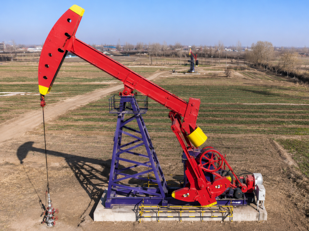
Sucker rod pump monitoring is an important IoT application in artificial lift operations, particularly at wells equipped with beam pumping units. A dynamometer system collects polished rod load and displacement data during the pumping cycle, together with stroke information and upper and lower dead-point switching signals. These measurements are transmitted to the dynamometer card acquisition host, where the signals are processed to generate surface dynamometer cards. By reviewing the load-displacement relationship and associated operating data, operators can assess pumping conditions and identify changes in equipment loading and operating behavior.
| Data Item | Measurement or Acquisition Method | Operational Purpose |
|---|---|---|
| Polished Rod Load | Load sensor | Records polished rod loading during the pumping cycle |
| Displacement | Displacement measurement arrangement | Records polished rod position and movement |
| Stroke Information | Acquired position and stroke signals | Reviews pumping stroke information |
| Upper and Lower Dead-Point Switching Signals | Switching signal acquisition | Identifies signals associated with stroke endpoints |
| Surface Dynamometer Card | Combined load and displacement data | Reviews load-displacement behavior during the pumping cycle |
Dynamometer Card Acquisition and Data Review
A surface dynamometer card plots polished rod load against displacement throughout a pumping cycle. It provides a visual representation of the pumping unit’s surface loading behavior, allowing engineers to review load-displacement patterns, compare changes between operating periods, and identify operating conditions that may require further investigation. However, a surface dynamometer card represents measurements taken at the polished rod and does not directly measure downhole pump conditions. Evaluating downhole performance also requires consideration of rod-string characteristics and relevant well operating information.
Remote Sucker Rod Pump Monitoring
When data from the dynamometer acquisition system is transmitted to a centralized monitoring platform through a supported communication interface, authorized personnel can remotely review surface dynamometer cards and associated polished rod load, displacement, and stroke data. The information available for remote review depends on the installed acquisition equipment, communication link, and software configuration.
Progressive Cavity Pump (PCP) Monitoring
Progressive Cavity Pumps operate through the interaction of a helical rotor and stator. Their operating conditions and data acquisition arrangements differ from those of conventional beam pumping units. An IoT monitoring system can connect the PCP function module with the available control terminal and equipment information to organize operating records and support remote review.
The main application areas include:
| Application Area | Information Managed | Operational Purpose |
|---|---|---|
| PCP Equipment Configuration | Equipment identification, model, configuration, and technical information | Maintains individual PCP equipment records and distinguishes different equipment configurations |
| PCP Operating Data Management | Operating information available from connected control terminals and configured measurement devices | Organizes acquired operating data for remote review and operating-condition assessment |
| Operating Records and Maintenance Management | Equipment records, well operating history, and recorded operating conditions | Supports equipment assessment, maintenance planning, and investigation of operating abnormalities |
The actual data fields depend on the installed controller, sensors, and communication interfaces. Parameters such as torque, rotational speed, motor current, and temperature should only be included when the specific system configuration supports their acquisition. Compatibility between the PCP control equipment, data acquisition terminal, and monitoring platform should also be verified during system integration.
Acoustic Liquid Level Measurement
Well liquid-level monitoring provides information about the fluid level inside an oil well and helps engineers evaluate well operating conditions.
An acoustic liquid level tester uses acoustic pulse generation and reflected signal analysis to determine the liquid-level depth. The instrument analyzes the returning acoustic signals to identify the response associated with the liquid interface.
Acoustic Measurement Process:Acoustic Pulse Generation → Pulse Transmission into the Well → Reflection from Internal Well Features and Liquid Interface → Echo Reception and Signal Analysis → Liquid-Level Depth Determination → Measurement Data Available for Well-Condition Review
The accuracy of the interpretation can be affected by well geometry, acoustic conditions, gas-column characteristics, and the quality of the reflected signal.
It is also important to distinguish liquid-level measurement from production-rate measurement. An acoustic liquid level tester determines fluid-level information; it does not directly measure oil or gas production flow rates.
Different Monitoring Instruments and Their Measurement Tasks
The monitoring instruments and modules used in oilfield production serve different measurement and equipment-management purposes. Their functions should be distinguished by the physical quantities measured, the data outputs provided, and the equipment or operation being monitored.
| Instrument | Primary Measurement | Main Data Output | Operational Application |
|---|---|---|---|
| Split-Type Dynamometer | Polished rod load and displacement | Surface dynamometer card, stroke and load information | Beam pumping unit performance review |
| All-in-One Wireless Dynamometer | Load and displacement, according to its configuration | Dynamometer measurement data | Wireless pumping-unit monitoring |
| Acoustic Liquid Level Tester | Acoustic reflections associated with the well liquid level | Liquid-level depth information | Well liquid-level evaluation |
| PCP Monitoring Module | Available controller and configured equipment signals | Supported PCP operating information | PCP operating condition review |
The selection of an instrument should be based on the actual measurement objective, required data outputs, and compatibility with the installed equipment and communication configuration, rather than treating all monitoring devices as interchangeable.
How Does Remote IoT Monitoring Improve Oilfield Production Management?
Remote IoT Monitoring connects measurement data and equipment operating records from multiple oil wells to a centralized platform. Production personnel can remotely review well conditions, compare equipment performance, and access historical operating information without relying entirely on individual site inspections.
Multi-Well Data Integration and Production Review
An IoT monitoring platform organizes available field data according to well, equipment, measurement type, and recording time. This allows engineers to compare operating conditions across multiple wells and identify changes in measurement trends.
| Data Category | Information Collected | Management Purpose |
|---|---|---|
| Well Information | Well identification and associated records | Distinguishes individual production wells |
| Equipment Data | Equipment identity and technical specifications | Maintains equipment records |
| Measurement Data | Load, displacement, and liquid-level measurements | Supports operating-condition assessment |
| Operating History | Historical measurements and operating events | Tracks changes over time |
| Maintenance Records | Inspection and maintenance information | Supports maintenance planning |
One important distinction is that equipment monitoring data does not necessarily represent actual production volume. Load, displacement, and liquid-level measurements describe equipment operation and well conditions. Oil and gas production rates require separate measurement sources, such as flowmeters, metering systems, or validated well-test records.
Equipment and Operating History Management
By associating equipment records with individual wells, the monitoring platform allows engineers to review equipment specifications, operating history, and reported problems together.
| Management Function | Information Reviewed | Operational Purpose |
|---|---|---|
| Equipment Record Review | Equipment identification, specifications, and well assignment | Verifies equipment information |
| Operating History Tracking | Historical measurements and operating events | Identifies changes in equipment operation |
| Maintenance Planning | Inspection records and reported problems | Identifies equipment requiring further assessment |
Changes in recorded operating parameters, such as polished rod load and displacement, can be compared with historical data to investigate recurring problems. These records also help maintenance personnel plan inspections and servicing across multiple wells.
Remote monitoring supports equipment assessment but does not replace physical inspection or mechanical evaluation.
How Does RFID Support Oilfield Equipment Identification and Lifecycle Management?
RFID identification provides an equipment traceability function within an oilfield IoT management system. Unlike dynamometers and acoustic liquid level testers, which collect operating measurements, RFID chips identify individual equipment components and associate their physical identities with digital records. This approach can be applied to selected production equipment, including sucker rods, polished rods, tubing, sucker rod pumps, and polished rod sealing devices, allowing equipment information to be retrieved and maintained throughout its service life.
Equipment Identification and Digital Records
Each registered RFID chip is associated with an individual equipment record in the management platform. When the chip identification information is retrieved, the corresponding record provides access to the equipment number, name, specifications, manufacturer, and other recorded technical and usage information. This allows individual components to be distinguished even when they belong to the same equipment category or have similar specifications.
Equipment Information Fields
| Information Field | Recorded Information | Management Purpose |
|---|---|---|
| Equipment Number | Individual equipment identification number | Distinguishes individual components |
| Equipment Name | Component or product name | Identifies equipment category |
| Specification | Equipment specification and model | Provides technical identification |
| Manufacturer | Manufacturing information | Maintains manufacturing traceability |
| Length | Recorded component length | Supports dimensional records and engineering calculations |
| Maximum Load | Maximum load information | Maintains equipment load-related data |
| Number of Runs | Recorded equipment usage count | Tracks equipment utilization history |
Equipment Lifecycle Tracking
After registration, the RFID identification record remains associated with the corresponding physical component throughout its service life. The management platform can organize equipment records across manufacturing, RFID registration, logistics and storage, well assignment, downhole operation, pull-out, inspection, maintenance, and end-of-life stages. When equipment is transferred between locations, assigned to a well, retrieved from service, or inspected, the relevant records can be updated to maintain a traceable history of its use and handling.
Equipment Lifecycle Flow:
Manufacturing → RFID Registration → Logistics and Storage → Well Assignment → Downhole Operation → Pull-Out and Inspection → Maintenance or End-of-Life
By maintaining these records under the same equipment identification number, the platform provides a continuous reference for reviewing equipment ownership, well assignment, operating history, and service status.
Equipment Quality and Maintenance Tracking
For sucker rods, polished rods, tubing, and related pumping equipment, RFID-linked records can support quality tracking and equipment condition analysis. Recorded information such as leakage, corrosion, eccentric wear, inspection findings, and service-life changes can be associated with individual equipment records, making it easier to review recurring problems and identify components requiring further inspection. For polished rod sealing devices, the same management approach can also support packing replacement planning by using recorded equipment history and well operating information to organize maintenance reminders.
RFID itself does not detect corrosion, measure wear, or determine the remaining service life of a component. These conditions must be established through appropriate inspection, measurement, and maintenance procedures and then associated with the equipment record. RFID provides the identification and traceability link that connects physical equipment with its quality, usage, and maintenance history, complementing the measurement and production monitoring functions of the wider IoT system.
What Should Be Considered When Selecting an IoT Oilfield Monitoring System?
Selecting an IoT oilfield monitoring system starts with defining the wells and equipment to be monitored, the required measurements, and how field data will be collected and managed. Beam pumping units, sucker rod pump systems, and progressive cavity pumps (PCPs) have different operating characteristics and data acquisition requirements. The selected instruments, acquisition terminals, communication interfaces, and software therefore need to be evaluated as a complete configuration.
Equipment and Monitoring Requirements
The first step is to identify the production equipment and monitoring objectives. Different applications require different measurement instruments and equipment identification arrangements. The following items should be clarified before determining the system configuration.
| Selection Item | Information to Confirm |
|---|---|
| Well Types | Oil wells, gas wells, water wells, and associated production equipment |
| Artificial Lift Equipment | Beam pumping units, sucker rod pump systems, and PCP systems |
| Monitoring Objectives | Polished rod load, displacement, stroke information, liquid level, and available operating signals |
| Equipment Identification | RFID identification requirements and equipment record fields |
| Data Management | Well records, equipment history, and maintenance information |
The monitoring objectives should be defined according to the actual equipment and measurement requirements. For example, polished rod load and displacement require appropriate dynamometer measurement arrangements, while well liquid-level monitoring requires a suitable acoustic liquid level tester. Equipment identification and operating measurement are separate functions and should be configured accordingly.
Instrument and Communication Compatibility
After defining the monitoring requirements, the next step is to verify compatibility between field instruments, data acquisition terminals, communication equipment, and the monitoring platform. A measurement instrument must provide signals that the connected acquisition equipment can receive and process. Communication arrangements and power requirements must also match the installation conditions.
| Verification Item | Key Considerations |
|---|---|
| Instrument Configuration | Confirm the measurement instruments required for each application |
| Signal Compatibility | Verify sensor outputs and acquisition terminal input requirements |
| Communication Interface | Confirm wired or wireless communication arrangements |
| Power Supply | Review available power sources and field power requirements |
| Software Integration | Check compatibility with the existing monitoring platform |
| Environmental Conditions | Consider operating temperature, weather exposure, and applicable hazardous-area requirements |
The compatibility review should cover the complete connection from the field instrument to the monitoring platform. The availability of a measurement parameter or communication function should be confirmed through the technical documentation of the selected equipment rather than assumed from the general system description.
Data Management and System Integration
Beyond instrument compatibility, the monitoring platform must correctly associate collected information with the corresponding well and equipment records. Historical data retrieval, measurement timestamps, equipment identification, and data export should be checked to determine whether the platform can support the intended production management process.
| Data Management Item | What to Verify |
|---|---|
| Historical Data Retrieval | Whether historical measurement records can be retrieved for review |
| Record Identification | Whether well and equipment identifiers are correctly associated with each record |
| Timestamp Management | Whether measurement timestamps are accurately recorded |
| Alarm Configuration | Whether alarm conditions can be configured for the intended application |
| Data Export and Integration | Whether collected data can be exported or integrated with existing management systems |
| User Access and Backup | Whether user permissions and data backup arrangements are defined |
| System Maintenance | Whether system maintenance responsibilities and arrangements are established |
The final configuration should be verified against actual field conditions and the technical documentation of the selected instruments, acquisition terminals, and communication equipment. Measurement parameters, alarm functions, and integration options should only be included when supported by the corresponding hardware and software configuration.
OCTAL provides IoT-based oilfield monitoring and equipment management solutions for oil and gas production operations. Depending on project requirements, the system can integrate dynamometer data acquisition, acoustic liquid-level measurement, PCP monitoring, intelligent control, and RFID-based equipment identification. OCTAL can configure the system according to the production equipment, required monitoring functions, and field operating conditions.
FAQ
Q:What Data Can an IoT Oilfield Monitoring System Collect?
A:An IoT oilfield monitoring system collects data according to the connected instruments and equipment interfaces. Typical data includes polished rod load, displacement, stroke information, well liquid level, and available PCP operating signals. RFID can also link equipment identification and maintenance records to the monitoring platform.
Q:Can an IoT System Monitor Multiple Oil Wells Remotely?
A:Yes. A centralized IoT platform can collect and organize data from multiple wells when each site has compatible acquisition equipment and communication connections. Operators can review well-specific measurements, compare operating histories, and access equipment records remotely.
Q:Does IoT Oilfield Monitoring Measure Oil Production Rates Directly?
A:Not necessarily. Dynamometers measure polished rod load and displacement, while acoustic liquid level testers determine fluid-level depth. Direct production-rate measurement requires suitable flowmeters, metering systems, or validated well-test data connected to the monitoring platform.
Q:What Is the Role of RFID in Oilfield Equipment Monitoring?
A:RFID identifies individual components and links them to digital equipment records, including specifications, usage history, inspection, and maintenance information. It supports equipment traceability but does not directly measure corrosion, wear, or remaining service life.