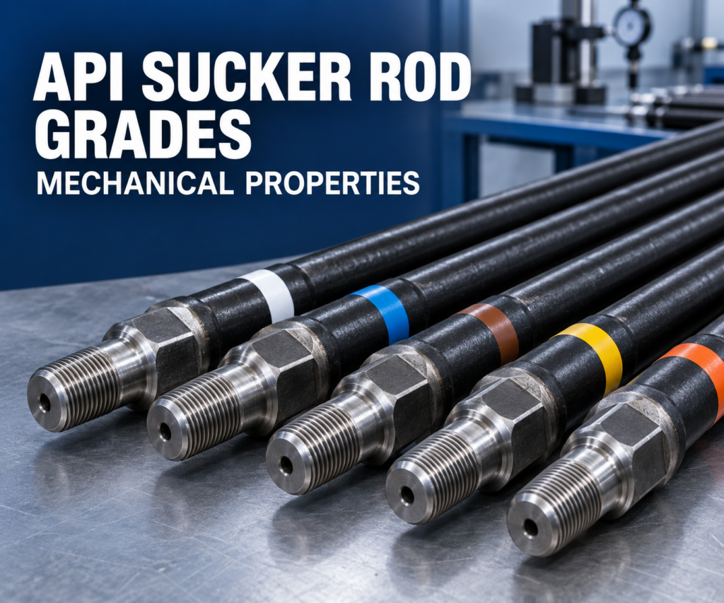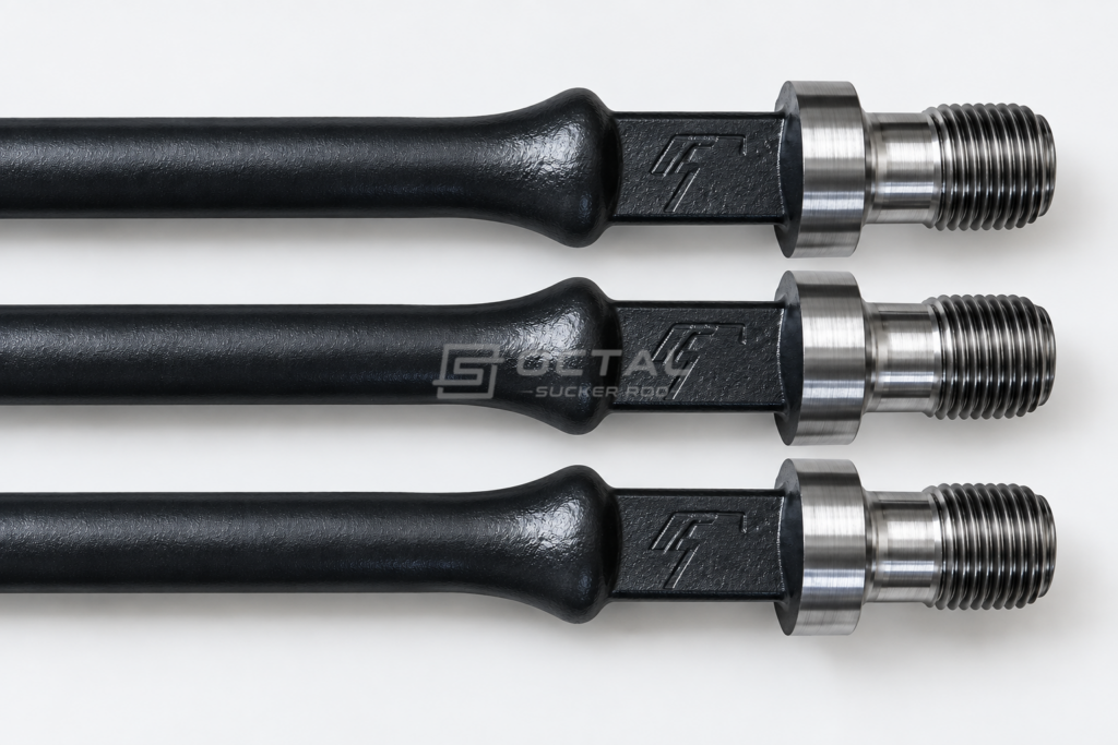
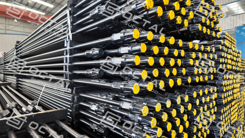
Sucker rods are steel rods with threaded ends, joined by couplings to form a continuous rod string inside production tubing. They transmit reciprocating motion and tensile loads from the surface pumping unit to the downhole pump. Commonly manufactured in API 11B grades such as C, K and D, sucker rods are used in artificial lift systems for oil wells that require mechanical assistance to bring fluids to the surface.
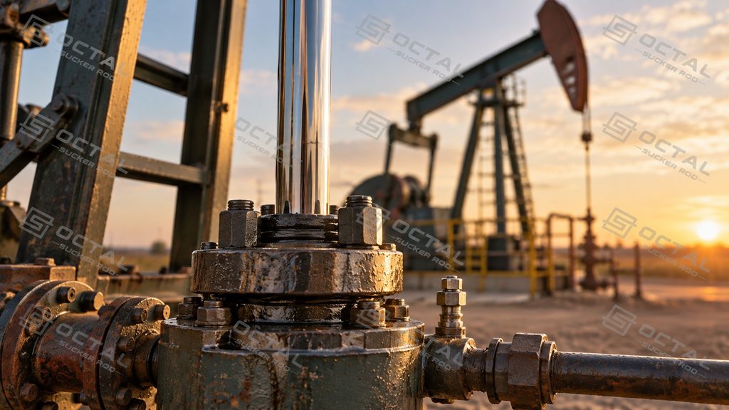
Polished rods are precision-finished steel rods installed at the upper end of the sucker rod string. Their smooth, wear-resistant working surface passes through the wellhead stuffing box to maintain a dynamic seal during reciprocating movement. They connect the surface pumping equipment to the downhole rod string while carrying the combined loads generated during pumping operations.
Both components are essential to conventional rod-pumping systems, particularly in onshore oil production and mature fields with declining reservoir pressure. However, polished rods and sucker rods differ in installation position, dimensions, connections and operating conditions, making their selection dependent on well depth, pumping loads, corrosion exposure and equipment compatibility.
What Is the Difference Between a Polished Rod and a Sucker Rod?
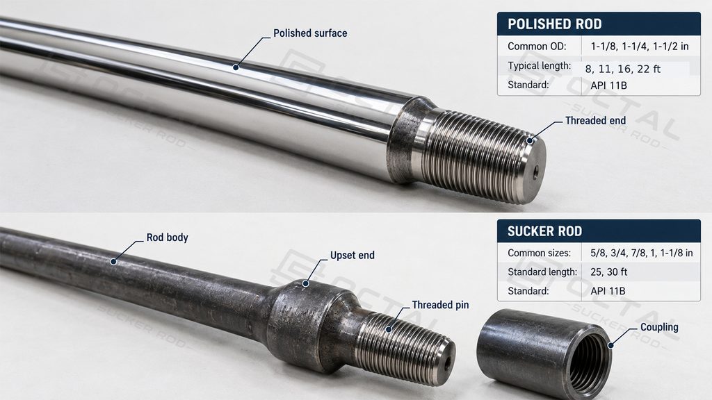
The primary difference lies in their operating positions and contact conditions. A polished rod works at the surface, where it must carry the rod-string load while maintaining a seal against the stuffing-box packing. A sucker rod operates within the tubing, transmitting motion between the surface assembly and the downhole pump through a series of connected rods.
Their differences extend to material selection, dimensions, surface treatment and inspection requirements.
| Comparison | Polished Rod | Sucker Rod |
|---|---|---|
| Installation position | Top of rod string, passing through the wellhead | Inside production tubing |
| Primary function | Transfers surface loads and provides a dynamic sealing surface | Transmits reciprocating loads to the downhole pump |
| Common diameters | 1-1/8, 1-1/4, 1-1/2 in. | 5/8, 3/4, 7/8, 1, 1-1/8 in. |
| Typical lengths | 8, 11, 16, 22 ft | 25, 30 ft |
| Material options | Carbon steel, alloy steel, corrosion-resistant constructions | Steel grades C, K, D and other specified grades |
| Surface requirements | Precision-finished working surface | Controlled rod-body finish and connection geometry |
| Connection arrangement | Polished-rod end connections and suitable adapters | Standardized pins and couplings |
| Main operating concerns | Packing leakage, surface wear, bending and clamp damage | Fatigue, corrosion, buckling, coupling wear and tensile loading |
| Applicable standard | API Spec 11B, where specified | API Spec 11B |
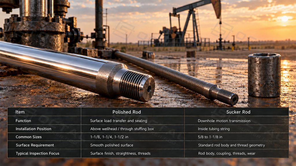
A polished rod is not simply a sucker rod with a smoother surface. Its diameter, load-bearing arrangement and sealing function are specifically suited to the upper end of the rod-lift system. Conventional sucker rods do not have the same continuous precision-finished sealing surface and should not be substituted for polished rods.
How Polished Rods and Sucker Rods Work Together
A conventional sucker rod pump converts the rotary motion of a surface drive into reciprocating movement through a pumping unit and rod string. The polished rod transfers the motion from the surface assembly to the connected sucker rods, which operate the reciprocating downhole pump.
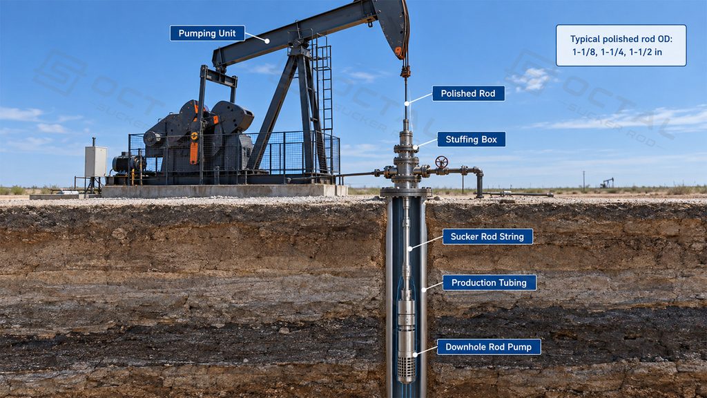
During the upstroke, the surface unit raises the rod string. The polished rod carries the resulting tensile load through the carrier bar and clamp arrangement, while the sucker rods transmit the upward movement to the downhole pump plunger.
During the downstroke, the rod string moves downward under the combined effects of its weight, pump conditions and dynamic forces. The relative loading changes throughout the cycle, particularly as stroke speed, fluid load and rod-string acceleration vary.
The principal components work together as follows:
| Component | Function |
| Surface Pumping Unit | Produces reciprocating motion and supports the polished-rod load. |
| Polished Rod | Transfers motion through the wellhead while providing a smooth sealing surface. |
| Sucker Rod String | Connects individual rods to transmit reciprocating movement downhole. |
| Downhole Rod Pump | Uses plunger movement and check valves to lift produced fluids through the production tubing. |
Differences in Size and Connection Design
Polished Rod Dimensions and Length Selection
Polished rods generally have a larger diameter than the upper section of the sucker rod string because they must carry the rod-string load while operating through the stuffing box.
Common polished rod diameters are 1-1/8, 1-1/4 and 1-1/2 inches, although additional sizes are available for particular equipment configurations.
| Polished Rod Diameter | Metric Equivalent | Common Length Options |
|---|---|---|
| 1-1/8 in. | 28.58 mm | 8, 11, 16, 22 ft |
| 1-1/4 in. | 31.75 mm | 8, 11, 16, 22 ft |
| 1-1/2 in. | 38.10 mm | 8, 11, 16, 22 ft |
These are representative size and length combinations. Availability and dimensional tolerances must be confirmed against the specified product standard and supplier catalogue.
Length selection depends on the pumping-unit stroke, carrier-bar position, stuffing-box installation and the required clearance at both ends of travel. The polished surface must cover the complete travel path through the packing.
A polished rod that is too short can place an unsuitable end section or connection near the stuffing box during operation. Excessive unsupported length may introduce additional handling and alignment difficulties.
Sucker Rod Sizes and Connections
Individual sucker rods are joined by threaded couplings to form a continuous rod string. Their body diameter and connection dimensions are coordinated to carry cyclic tensile loads while maintaining adequate clearance inside production tubing.
Common steel sucker rod dimensions include:
| Nominal Rod Diameter | Metric Diameter | Typical API Pin Size |
|---|---|---|
| 5/8 in. | 15.88 mm | 15/16 in. |
| 3/4 in. | 19.05 mm | 1-1/16 in. |
| 7/8 in. | 22.23 mm | 1-3/16 in. |
| 1 in. | 25.40 mm | 1-3/8 in. |
| 1-1/8 in. | 28.58 mm | 1-9/16 in. |
Standard rod lengths commonly include 25 ft and 30 ft. Shorter pony rods may be used to adjust the total rod-string length.
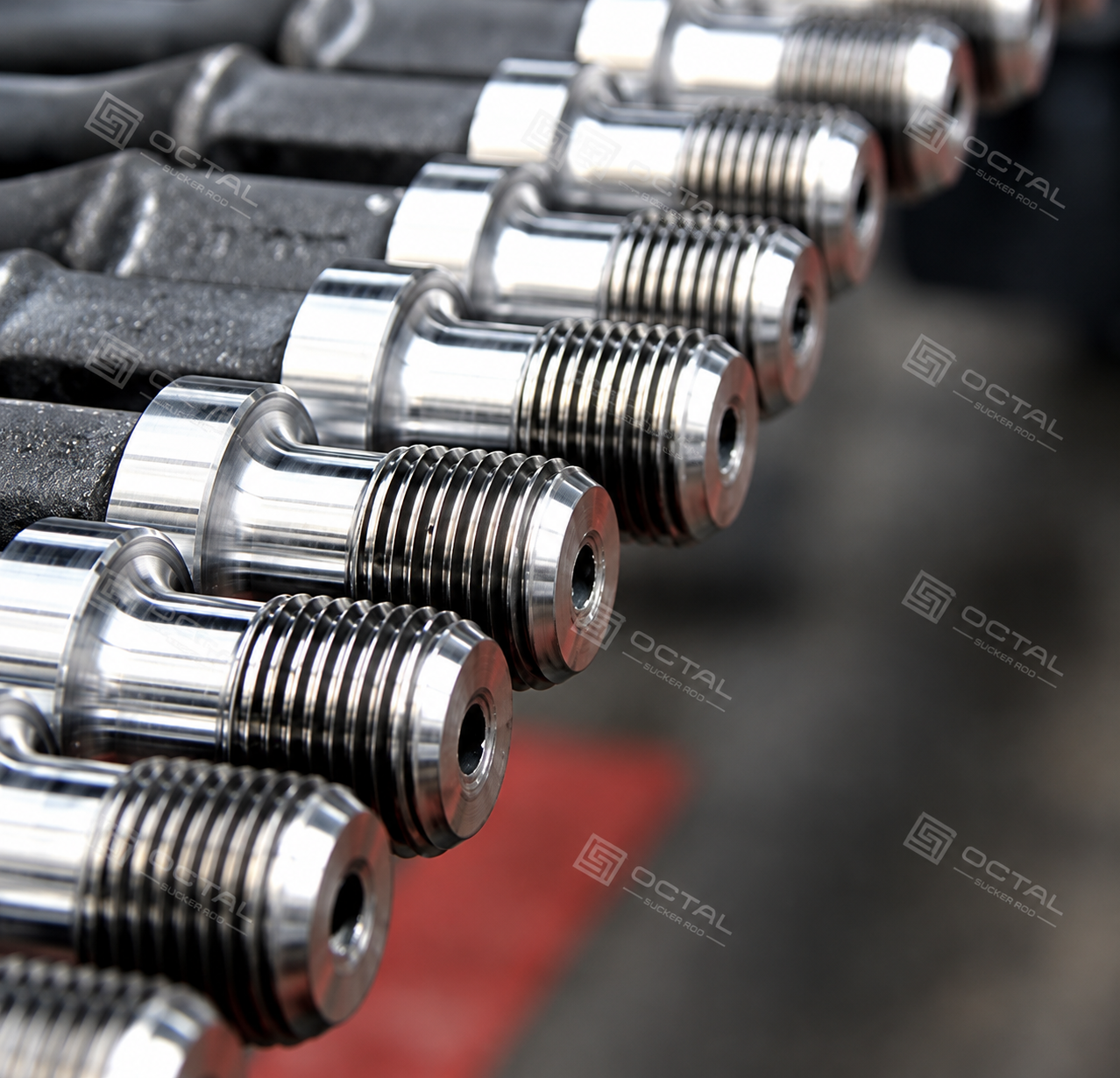
A larger rod diameter increases the nominal steel cross-sectional area and therefore changes the tensile load capacity and string weight. It also affects the clearance within production tubing and the total suspended load carried by the surface equipment.
Connection compatibility requires more than matching nominal rod diameter. Pin dimensions, thread form, coupling type and shoulder condition must conform to the specified connection system.
At the transition between polished rod and sucker rod, the connection arrangement must match both components. Polished-rod threads are not necessarily interchangeable with ordinary sucker-rod coupling threads.
Material Strength and Surface Requirements
Material selection for polished rods and sucker rods follows different priorities.
Polished Rod Material and Surface Finish
A polished rod must withstand the full suspended rod-string load while maintaining a smooth, durable surface for repeated movement through the stuffing-box packing.
Carbon steel and alloy steel are commonly used, with corrosion-resistant materials or surface treatments selected where operating conditions require additional protection.
Surface finish is especially important. Scratches, pitting, hard deposits or coating damage can accelerate packing wear and create leakage paths.
Some polished rods use a spray-metal coating to improve surface wear and corrosion resistance. The coating must remain compatible with the stuffing-box packing and the intended service conditions.
Strength alone is insufficient for selection. Rod straightness, surface condition, corrosion resistance and the relationship between the polished diameter and stuffing-box bore also influence service reliability.
Sucker Rod Grades and Mechanical Properties
Steel sucker rods are supplied in different material grades to accommodate mechanical loading and corrosion conditions.
| Sucker Rod Grade | General Material Characteristics | Selection Consideration |
|---|---|---|
| Grade C | Moderate-strength steel grade | Conventional loading where its rated properties are adequate |
| Grade K | Corrosion-resistant grade with defined mechanical requirements | Specific corrosive service, subject to fluid compatibility |
| Grade D | Higher-strength steel grade | Higher rod-string loads where fatigue and corrosion conditions are acceptable |
| High-strength grades | Manufacturer- and specification-dependent properties | Higher tensile demand requiring detailed fatigue and service verification |
Load Transmission and Mechanical Stress
The loading of polished rods and sucker rods changes throughout each pumping cycle. The polished rod carries the combined surface load generated by rod-string weight, fluid loading, acceleration and friction. Its tensile load varies with pumping-unit motion and downhole pump conditions.
Sucker rods experience different axial loads along the string, with higher tensile loads generally occurring toward the upper sections. Rod diameter, material strength and connection design determine load-bearing capacity, while repeated stress cycles, bending and corrosion influence fatigue performance.
A larger rod diameter reduces nominal axial stress under the same tensile force but also increases the suspended string weight. Actual rod-string performance must therefore account for dynamic loading, connection stress concentrations and fatigue rather than relying on tensile strength alone.
| Operating Condition | Polished Rod Response | Sucker Rod Response |
|---|---|---|
| High fluid load | Increased surface tensile load | Increased axial load transmitted through the string |
| Long pumping stroke | Greater travel through stuffing-box packing | Repeated axial movement and changing dynamic loads |
| Pumping-unit misalignment | Bending and uneven sealing contact | Additional lateral loading near the upper string |
| Corrosive fluids | Surface pitting and seal deterioration | Rod-body and connection corrosion fatigue |
| Sand production | Abrasive damage at the sealing interface | Rod and coupling wear, especially where contact occurs |
For a given pumping system, polished-rod load measurements provide useful information about total operating loads. However, predicting downhole rod stress requires consideration of rod-string design, fluid conditions, pump behavior and dynamic effects.
Wear, Corrosion and Common Failure Locations
The difference between polished rod and sucker rod wear is closely related to their contact surfaces.
A polished rod moves repeatedly through a relatively fixed packing assembly. Excessive side loading or poor surface condition can produce localized wear along the polished surface. Leakage may develop even when the rod retains sufficient tensile strength.
Misalignment between the pumping-unit carrier assembly and the stuffing box can increase lateral contact forces. Clamp installation is another important consideration because clamping forces and local surface damage may introduce stress concentrations.
Sucker rods encounter different wear mechanisms inside the wellbore.
In deviated wells, rod bodies and couplings may contact the inner wall of production tubing. Repeated reciprocating movement can gradually remove material from the rod, coupling or tubing surface.
Corrosion can accelerate this process by creating surface discontinuities that act as fatigue initiation sites.
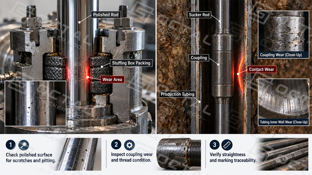
The most relevant inspection points therefore differ:
| Inspection Area | Polished Rod | Sucker Rod |
|---|---|---|
| Surface condition | Scratches, pitting, coating deterioration | Corrosion, wear and mechanical damage |
| Straightness | Important for stable stuffing-box sealing | Important for rod-string alignment and running |
| Connections | Thread condition and compatibility | Pin threads, shoulders and coupling condition |
| Dimensional condition | Diameter and applicable surface tolerances | Body diameter, end dimensions and thread geometry |
| Service damage | Packing-contact wear and clamp-area damage | Fatigue cracking, coupling wear and corrosion damage |
Visual inspection alone cannot establish remaining fatigue life. Additional dimensional or nondestructive examination may be required according to the inspection plan, product condition and applicable standard.
How to Select the Correct Rod for a Pumping System
Polished rod and sucker rod selection must begin with the pumping-system design, rather than treating either component as an independent replacement item.
For the polished rod, the principal considerations are the maximum anticipated polished-rod load, stuffing-box diameter, pumping stroke, material condition and connection arrangement.
The rod must have sufficient working length to remain properly engaged with the packing throughout the operating cycle. Its surface treatment should also be compatible with the well fluid and sealing system.
For the sucker rod string, design decisions depend on well depth, pump loading, stroke length, operating speed, tubing size, rod grade and anticipated corrosion or fatigue exposure.
A tapered rod string may use different rod diameters along its length to reduce unnecessary weight while maintaining adequate strength at heavily loaded sections. Each segment must be evaluated under its actual loading conditions.
Replacing either component without checking the complete assembly can introduce connection mismatch, excessive stress or premature wear.
The key selection principle is that the polished rod must satisfy surface load-transfer and sealing requirements, while the sucker rod string must transmit the required downhole motion and withstand cyclic service loads.
Polished Rod and Sucker Rod Supply
Octal’s rod-lift product range includes polished rods and sucker rods for oilfield production systems. Product requirements can be reviewed according to the specified API 11B provisions, dimensional configurations, material grades and connection arrangements.
For polished rods, particular attention is given to working-surface condition, diameter, straightness and end compatibility. Sucker rod specifications place additional emphasis on rod-body grade, pin dimensions, coupling compatibility and mechanical-property requirements.
Inspection and acceptance should follow the applicable purchase specification, with the corresponding material and dimensional records available for review.
FAQ
Q: Does a higher sucker rod grade improve fatigue life?
A: Not necessarily. Fatigue life depends on cyclic stress, corrosion, material properties and connection condition. Higher strength alone cannot prevent premature fatigue failure.
Q: How can sucker rod wear be reduced in deviated wells?
A: Properly positioned rod guides reduce rod-to-tubing contact. Optimizing rod-string design, controlling side loads and selecting suitable wear-resistant materials further minimize abrasion
Q: What causes polished rod leakage at the stuffing box?
A: Common causes include surface scratches, corrosion pitting, worn packing and misalignment. Regular inspection and proper packing adjustment help maintain reliable wellhead sealing.
Q: Can different sucker rod sizes be used in the same rod string?
A: Yes. Tapered rod strings combine different diameters to balance strength and weight. Each section must meet loading, fatigue, connection compatibility and tubing clearance requirements.