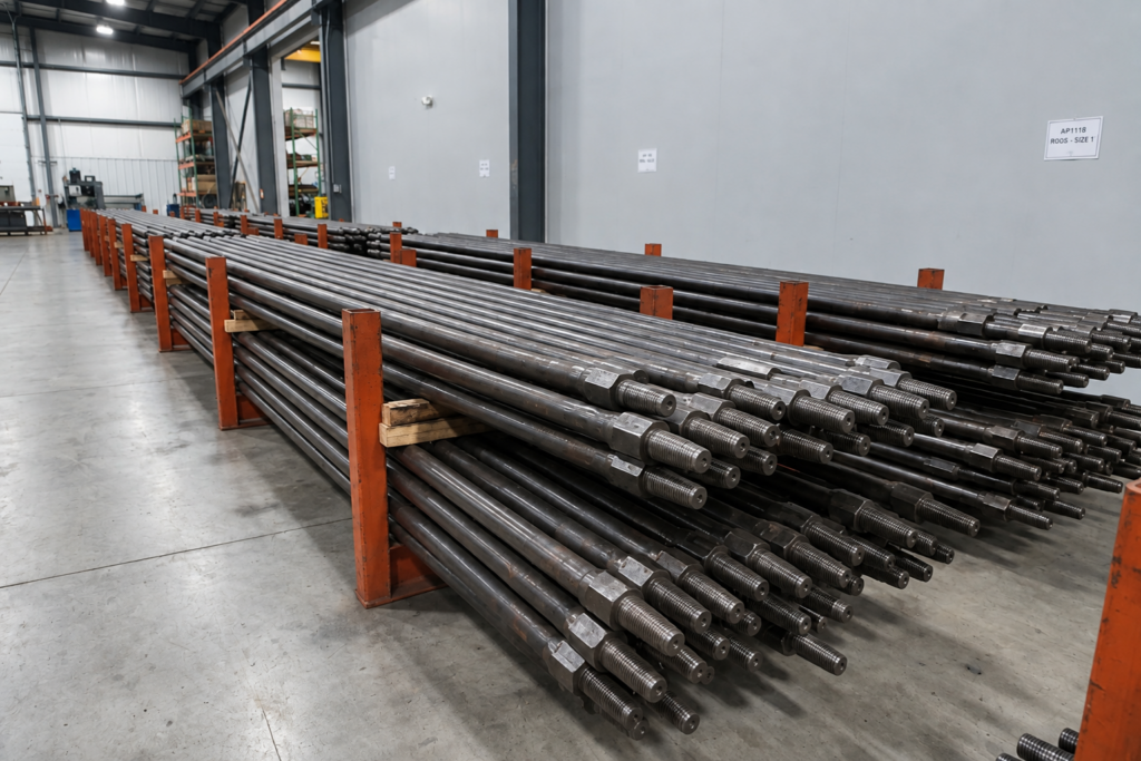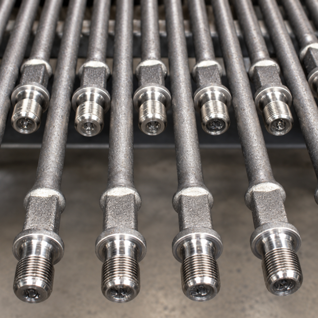
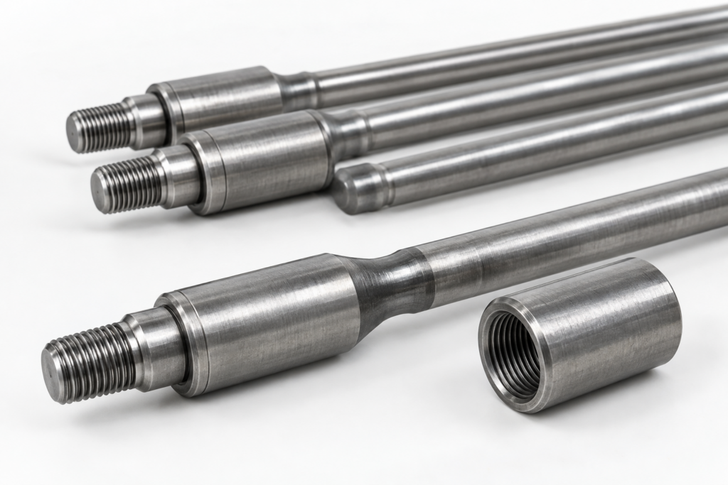
Sucker rods are API Spec 11B steel load-transfer components used in rod pumping systems to transmit reciprocating forces from surface pumping units to downhole pumps. Manufactured mainly from alloy steel with controlled chemical composition, heat treatment, and threaded connections, sucker rods are designed to withstand repeated tensile loading during artificial lift operations.
Installed as a continuous sucker rod string between the polished rod and the downhole pump, sucker rods transfer the vertical movement generated by the surface unit to the pump plunger, allowing produced fluids to be lifted from oil wells. Common steel sucker rod sizes range from 5/8 in. to 1-1/8 in. outside diameter, with standard lengths of 25 ft (7.62 m) and 30 ft (9.14 m). Unlike ordinary steel bars, sucker rods must maintain mechanical strength, connection integrity, and fatigue resistance under millions of cyclic loading operations.
The selection of sucker rods is not determined only by rod diameter. Engineers normally evaluate rod grade, well depth, tensile loading, corrosion environment, connection design, and inspection requirements to ensure the rod string matches the actual operating conditions.
Sucker Rod Structure and Main Components
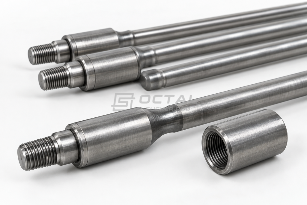
A sucker rod string is assembled from multiple individual rods connected by threaded couplings to form a continuous load-transfer member between the polished rod and the downhole pump. Although the rod string appears simple in configuration, its field performance depends on the interaction between the rod body, upset section, pin end, coupling, and spacing components. In practical service, the connection area is usually more critical than the straight rod body because cyclic loading, make-up quality, and stress concentration all act in this region.
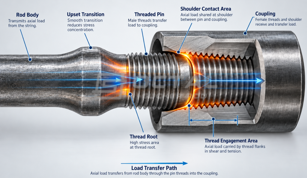
The main structural elements of a conventional sucker rod string are summarized below:
| Component | Primary Function | Engineering Importance |
| Rod body | Transfers axial tensile load through the well | Strength, straightness, and surface condition affect overall string reliability |
| Pin end | Provides the male threaded connection | Thread form accuracy directly influences load transfer and make-up performance |
| Coupling | Connects two rods into a continuous string | Connection strength and dimensional compatibility are essential for service integrity |
| Upset section | Increases cross-section near the connection area | Helps reduce stress concentration at the rod end |
| Pony rod | Provides short-length adjustment within the string | Used to fine-tune spacing and rod-string configuration |
From a mechanical standpoint, the connection zone is one of the most sensitive parts of a sucker rod. During repeated pumping cycles, the load is not distributed uniformly across the entire rod. Local stress concentration is more likely to occur at the thread root, shoulder area, and upset transition section, where geometry changes and connection loading are combined. For that reason, many field failures start near the connection rather than at the middle of the rod body.
This is also why sucker rod manufacturing control must go beyond simple diameter checking. In addition to rod body strength, manufacturers and buyers normally pay close attention to the following acceptance points:
| Control Item | Why It Matters |
| Thread machining accuracy | Affects connection fit, load distribution, and fatigue behavior |
| Surface condition | Surface defects can become fatigue initiation points |
| Connection compatibility | Mismatch between rod and coupling may reduce service reliability |
| Dimensional inspection | Confirms interchangeability and proper fit within the rod string |
For engineering and procurement work, the practical takeaway is clear: a sucker rod should not be evaluated only as a straight steel bar. Its service reliability depends heavily on connection geometry, upset-end quality, machining accuracy, and inspection control, because these factors determine how effectively the rod string can withstand cyclic loads over a long operating period.
Sucker Rod Sizes and API 11B Specifications
Sucker rods are commonly supplied according to API Spec 11B, which defines requirements for sucker rod dimensions, mechanical properties, and testing.
Common nominal sizes include:
| Nominal Sucker Rod Size | Rod Body Outside Diameter |
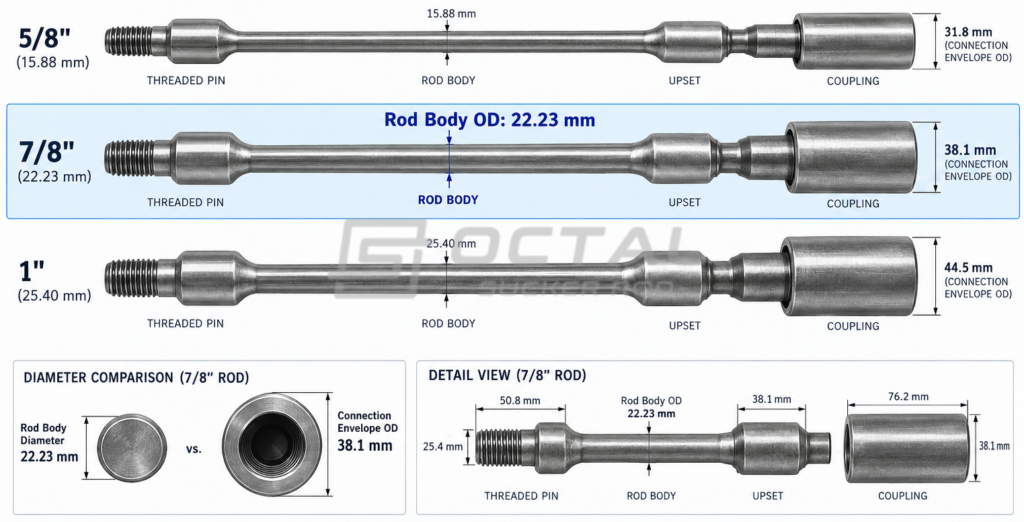
| 5/8 in. | 15.88 mm |
| 3/4 in. | 19.05 mm |
| 7/8 in. | 22.23 mm |
| 1 in. | 25.40 mm |
| 1-1/8 in. | 28.58 mm |
Standard rod lengths:
| Length | Metric Equivalent |
| 25 ft | 7.62 m |
| 30 ft | 9.14 m |
However, rod body diameter is only one part of the selection process.
A complete specification normally includes:
| Specification Item | Why It Matters |
| Grade | Determines allowable mechanical loading range |
| Nominal diameter | Affects rod string design |
| Length | Determines string configuration |
| Connection type | Ensures compatibility with couplings |
| Corrosion environment | Influences material selection |
| Inspection requirements | Defines acceptance before delivery |
A common purchasing mistake is selecting a sucker rod only by nominal diameter. In practice:
Rod Body OD ≠ Connection Envelope
The coupling outside diameter, thread configuration, and tubing clearance must also be considered.
How Do Sucker Rods Work in an Oil Well?
A sucker rod system transfers mechanical energy from the surface pumping unit to the downhole pump through a connected rod string. In a conventional rod-lift system, the basic load path is:
Surface Pumping Unit → Polished Rod → Sucker Rod String → Downhole Pump.
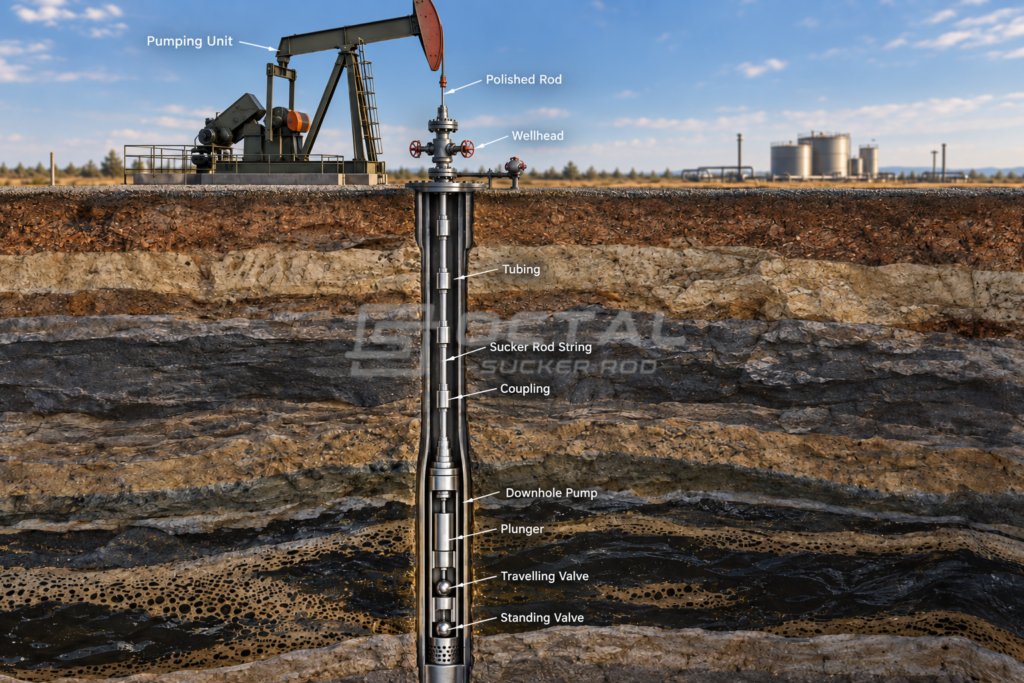
When the pumping unit moves, the polished rod transmits vertical reciprocating motion into the well. This motion is carried through the sucker rod string to the pump plunger, which creates the lifting action needed to bring produced fluids to the surface. In practical operation, the rod string does not work under a simple static load. It operates under repeated cyclic loading, with stress levels changing during every pumping stroke.
The basic operating cycle can be summarized as follows:
| Pumping Stage | Sucker Rod Function | Main Loading Condition |
| Upstroke | Pulls the pump plunger upward and lifts the fluid column | Tensile loading |
| Downstroke | Transfers downward motion and completes the pumping cycle | Compression and dynamic loading |
| Continuous operation | Repeats the lifting cycle over a long service period | Fatigue loading |
The actual load on the sucker rod string is influenced by several factors rather than by rod size alone. These factors determine whether the selected rod grade, diameter, and string design are suitable for the well.
| Load Factor | Effect on the Sucker Rod String |
| Rod string weight | Forms the base tensile load and increases with pump setting depth |
| Fluid load | Adds lifting resistance during the upstroke and affects peak rod stress |
| Pumping speed and stroke length | Increase dynamic loading and fatigue frequency |
| Well depth | Raises total string load and influences rod grade selection |
| Well deviation and tubing contact | Cause side loading, wear, and local stress concentration |
| Corrosive produced fluid | Reduces fatigue life and may accelerate connection failure |
Because these loads act repeatedly over a large number of cycles, sucker rods are selected and evaluated mainly on the basis of fatigue resistance, connection integrity, and service conditions, not tensile strength alone. A rod may satisfy nominal strength requirements but still fail early if well deviation, corrosion, poor alignment, or improper rod-string design is not properly controlled.
From an engineering perspective, this is why sucker rod selection normally considers more than diameter. The rod string must be matched to the actual operating environment, including well depth, pump load, stroke rate, fluid characteristics, deviation profile, and corrosion risk, so that both mechanical performance and service life remain within an acceptable range.
Sucker Rod Grades and Mechanical Properties
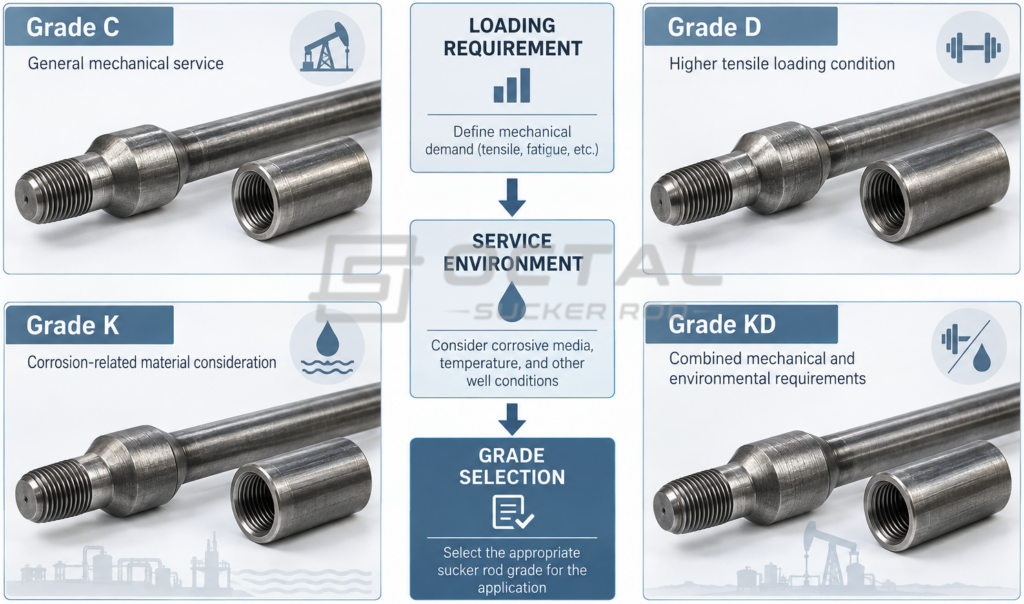
Different sucker rod grades are selected according to mechanical loading requirements and service conditions.
Typical API 11B steel sucker rod grades include Grade C, Grade D, Grade K, and Grade KD.
| Grade | Yield Strength | Tensile Strength | Main Selection Consideration |
| Grade C | 414 MPa | 621–793 MPa | Moderate mechanical loading |
| Grade D | 586 MPa | 793–965 MPa | Higher tensile loading requirements |
| Grade K | Material selection related to corrosion conditions | — | Corrosion-related service evaluation |
| Grade KD | Higher strength with corrosion-related considerations | — | Combined mechanical and environmental requirements |
The grade selection should follow the actual well condition.
For example:
| Operating Condition | Main Evaluation Factor |
| Deeper well | Tensile loading and rod weight |
| Higher pumping load | Yield and tensile strength |
| Corrosive produced fluid | Material selection |
| Deviated well | Wear and contact conditions |
A higher grade does not automatically mean better performance in every application. The correct selection depends on calculated loads and service risks.
Materials and Manufacturing Process of Steel Sucker Rods
Most conventional sucker rods are manufactured from alloy steel because they must withstand repeated tensile loading, fatigue cycles, and connection stresses during oil well operation. The material selection, chemical composition, and heat treatment process directly affect mechanical properties such as strength, toughness, and fatigue resistance.
The manufacturing process typically includes steel preparation, upsetting or forging of the connection area, heat treatment, straightening, thread machining, and inspection. Among these steps, the connection area requires particular attention because thread accuracy and surface condition directly influence load transfer and fatigue performance.
Types of Sucker Rods
Steel sucker rods are the most common type used in conventional rod pumping systems because they provide a practical balance between mechanical strength, fatigue resistance, and field reliability. However, different sucker rod designs have been developed for specific operating conditions, depending on well depth, loading requirements, production method, and installation limitations.
Conventional steel sucker rods are manufactured from alloy steel and are widely used in beam pumping applications. They are selected when the rod string requires reliable tensile strength, threaded connections, and long-term performance under repeated loading cycles.
Hollow sucker rods have a different internal structure that allows fluid flow through the rod body in specific pumping applications. Compared with conventional solid rods, they are evaluated based on their internal passage requirements, mechanical loading capacity, and compatibility with the pumping system.
Fiberglass sucker rods are designed for applications where reducing rod-string weight is beneficial. Their lower density can reduce the overall load on the pumping unit, but their mechanical behavior and installation requirements differ from steel sucker rods.
Continuous sucker rods use a continuous rod design instead of multiple individual rods connected by couplings. By reducing the number of threaded connections, they can change the connection-related maintenance requirements in certain applications.
The selection of sucker rod type depends on the complete operating condition, including:
- Required load capacity
- Well depth and deviation
- Pumping system design
- Corrosion environment
- Installation and maintenance requirements
Therefore, the most suitable sucker rod type is determined by the overall rod-string design and well conditions rather than by material type alone.
Engineering Considerations for Sucker Rod Selection
Selecting a suitable sucker rod requires evaluation of the complete rod-pumping system rather than a single parameter such as rod diameter or grade. The actual operating condition, including mechanical loading, well environment, connection design, and documentation requirements, determines the appropriate rod-string configuration.
Mechanical loading is one of the primary factors affecting sucker rod selection. Engineers consider parameters such as rod string weight, pump load, stroke length, and pumping frequency because these factors directly influence tensile stress and fatigue cycles during operation. For deeper wells or higher production loads, the rod grade and string design must provide sufficient strength margin for repeated service.
Well conditions also affect the selection process. Vertical and deviated wells create different loading and wear conditions, especially where tubing contact may occur. Produced fluid characteristics, corrosion risk, and operating temperature should also be considered because environmental conditions can influence fatigue performance and connection reliability.
Connection requirements are another important consideration. The selected sucker rod must match the coupling type, thread design, and installation procedure to ensure proper load transfer throughout the rod string. Since connection areas experience higher stress concentration, thread accuracy and dimensional compatibility are critical for long-term performance.
For project procurement, technical documentation is also an important part of the selection process. A complete specification normally includes the required API standard, rod grade, nominal size, length, connection type, and inspection records to ensure the supplied sucker rods match the designed operating conditions.
FAQ
What standard covers sucker rods?
Sucker rods are mainly manufactured according to API Spec 11B, which defines requirements for dimensions, grades, mechanical properties, and testing.
What are sucker rods made of?
Most conventional sucker rods are produced from alloy steel. Their performance depends on chemical composition, heat treatment, mechanical properties, and manufacturing control.
What sizes are available for sucker rods?
Common sucker rod sizes include 5/8 in., 3/4 in., 7/8 in., 1 in., and 1-1/8 in., with standard lengths of 25 ft and 30 ft.
What is the difference between Grade C and Grade D sucker rods?
Grade D sucker rods provide higher mechanical strength than Grade C and are typically considered when calculated rod loading requires additional strength margin.