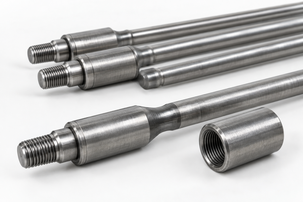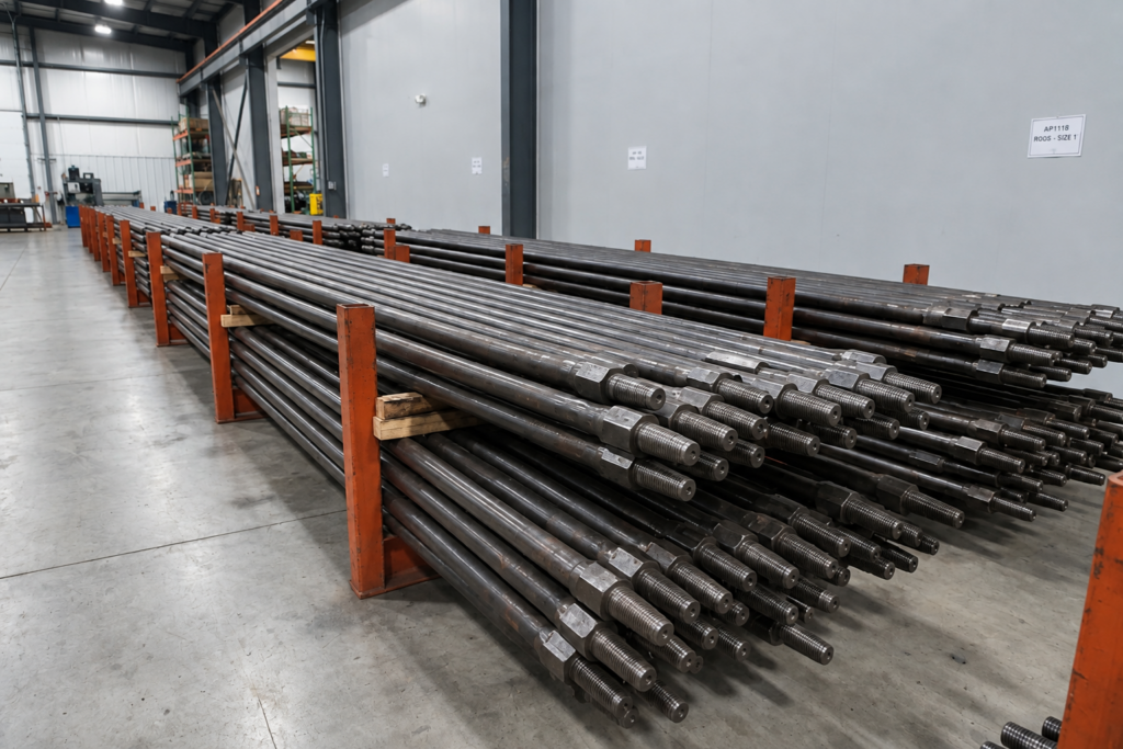
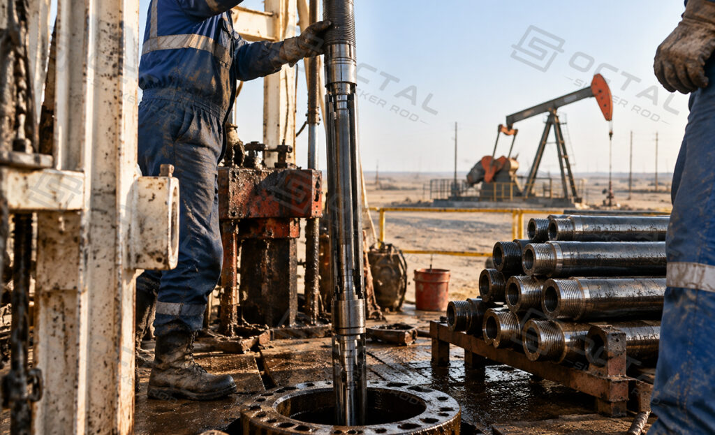
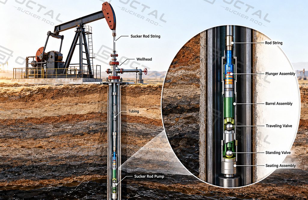
A sucker rod pump lifts oil and produced fluids from underground reservoirs through the reciprocating movement of a plunger inside a pump barrel. Installed in the production tubing, it uses a traveling valve and a standing valve to control fluid intake and displacement during each pumping cycle.
The pump operates as part of an artificial lift system. A surface pumping unit drives the sucker rod string, transferring vertical motion to the downhole pump. Its performance depends on pump diameter, stroke length, pumping speed, fluid properties, and downhole operating conditions.
Sucker rod pumps are commonly used in oil wells where natural reservoir pressure can no longer maintain the required production rate.
How Does a Sucker Rod Pump Work?
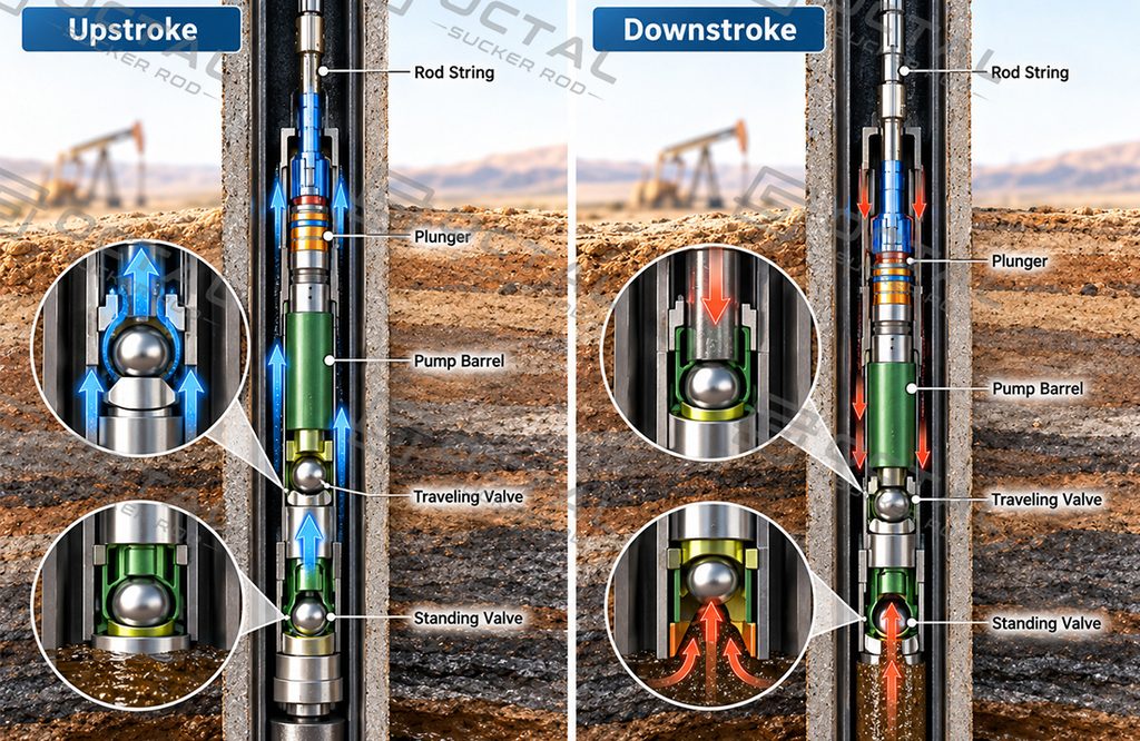
The sucker rod pump working principle is based on positive displacement. A plunger moves up and down inside a cylindrical barrel, while two check valves control the movement of well fluids.The traveling valve is installed in the moving plunger assembly, while the standing valve remains near the lower end of the barrel in a conventional stationary-barrel design.
Each pumping cycle consists of an upstroke and a downstroke.
Upstroke: Fluid Intake and Lifting
During the upstroke, the surface pumping unit pulls the sucker rod string upward, causing the plunger to rise inside the barrel.As the plunger moves upward, the traveling valve closes under the pressure difference across the plunger. This allows the liquid above it to be lifted through the production tubing.
Meanwhile, the expanding chamber below the plunger experiences a pressure reduction. When the pressure at the pump intake exceeds the pressure inside the chamber, the standing valve opens and reservoir fluid enters the barrel.
The amount of liquid admitted depends on pump intake pressure, available reservoir inflow, and effective plunger movement.If insufficient liquid enters the chamber, the pump experiences incomplete fillage, reducing its actual displacement.
Downstroke: Fluid Transfer
During the downstroke, the sucker rod string moves downward and the plunger descends inside the barrel.The standing valve closes as pressure inside the barrel increases, preventing the liquid from flowing back into the well.When the pressure below the traveling valve becomes sufficiently high, the traveling valve opens. Liquid then passes upward through the plunger into the tubing above it.At the bottom of the stroke, the pumping unit reverses direction and begins another cycle.
The valve actions can be summarized as follows:
| Pumping Stage | Traveling Valve | Standing Valve | Fluid Movement |
|---|---|---|---|
| Upstroke | Closed | Open | Liquid enters the barrel while the tubing fluid is lifted |
| Downstroke | Open | Closed | Liquid transfers through the plunger |
| Stroke Reversal | Valve states transition | Valve states transition | Pressure differences change before the next stroke |
Why Does Actual Pump Output Vary?
Although each pumping cycle produces a theoretical displacement, actual liquid production is generally lower.
The main factors include:
- Incomplete pump fillage: Insufficient reservoir inflow prevents the chamber from filling completely.
- Gas interference: Free gas compresses and expands inside the pump, reducing liquid displacement.
- Valve leakage: Worn valve balls or seats allow fluid to flow backward.
- Plunger wear: Excessive plunger-barrel clearance increases liquid slippage.
- Rod stretch: Elastic deformation reduces the effective downhole plunger stroke.
These factors explain why increasing pumping speed does not always increase production proportionally.
Main Components of a Sucker Rod Pump
A conventional downhole pump consists of a barrel, plunger, two check valves, and connecting components. Insert pumps additionally require a seating assembly to secure the pump inside the tubing.
| Component | Main Function |
|---|---|
| Pump Barrel | Provides the cylindrical working surface for plunger movement |
| Plunger | Displaces fluid through reciprocating motion |
| Traveling Valve | Controls fluid transfer through the moving plunger |
| Standing Valve | Allows fluid intake and prevents reverse flow |
| Valve Rod | Connects and transmits motion between applicable components |
| Seating Assembly | Anchors and seals an insert pump inside the tubing |
| Valve Cage | Houses the valve ball and guides fluid movement |
The plunger and barrel form the main pumping pair. Their running clearance must allow smooth movement while limiting leakage.Valve sealing is equally important. Sand particles, corrosion, or worn valve seats can prevent complete closure and reduce pumping efficiency.
Types of Sucker Rod Pumps
Sucker rod pumps are mainly classified into tubing pumps and insert pumps according to their installation and retrieval methods.
Tubing Pumps
A tubing pump has its barrel installed as part of the production tubing completion. The plunger is connected to the sucker rod string and moves inside the barrel.Tubing pumps can generally accommodate a larger working bore within a given tubing size, providing greater theoretical displacement.However, servicing the barrel normally requires retrieval of the tubing string.
Insert Pumps (Rod Pumps)
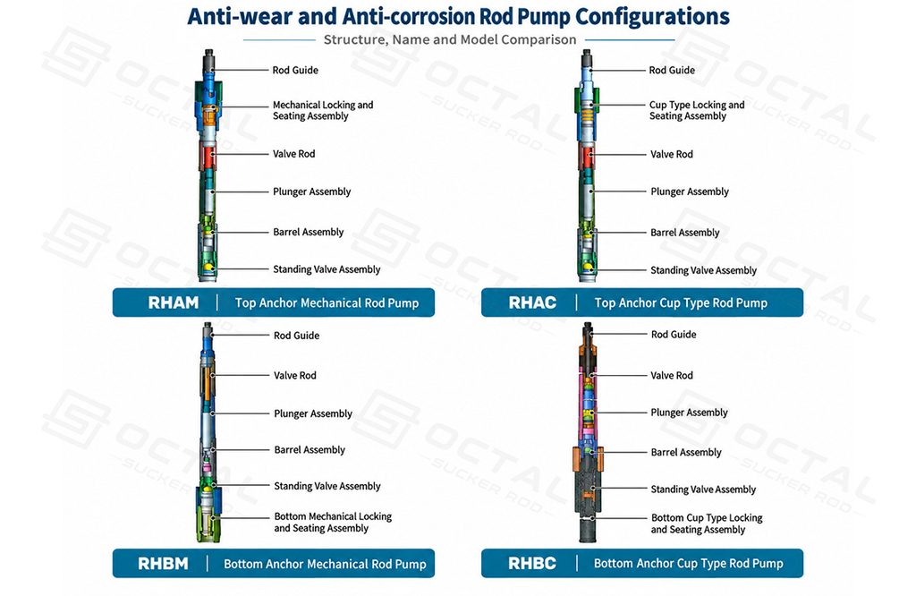
An insert pump is lowered into the production tubing with the sucker rod string and secured by a seating assembly.The complete pump can normally be retrieved with the rod string without removing the tubing, making inspection and replacement more convenient.Insert pumps are available with top-anchor, bottom-anchor, mechanical seating, and cup-type seating arrangements.
Specialty Sucker Rod Pumps
Specialized pump designs are developed for wells where sand, gas, or corrosive fluids interfere with conventional pumping.
| Pump Type | Structural Feature | Main Application |
|---|---|---|
| Long-Plunger Anti-Sand Pump | Extended plunger and short working barrel | Sand-producing wells |
| Sand-Settling Pump | Separate sand-settling flow arrangement | Wells with suspended solids |
| Hollow Anti-Gas Pump | Modified internal flow structure | Gas-prone wells |
| Forced Mechanical Valve Pump | Mechanically actuated valve arrangement | Severe gas interference |
| Anti-Wear and Anti-Corrosion Pump | Selected materials and treated working surfaces | Abrasive or corrosive fluids |
These designs address different operating problems and should be selected according to the actual well conditions.
Common Sucker Rod Pump Models
Conventional insert pumps are available in several configurations based on their seating position and anchoring mechanism.The supplied product range includes the following models.
| Model | Configuration |
|---|---|
| RHAM | Top-Anchor Mechanical Rod Pump |
| RHAC | Top-Anchor Cup-Type Rod Pump |
| RHAM-AC | Top-Anchor Double-Clip Rod Pump |
| RHBM | Bottom-Anchor Mechanical Rod Pump |
| RHBC | Bottom-Anchor Cup-Type Rod Pump |
The main differences concern the pump seating location and locking or sealing mechanism.These conventional models are complemented by anti-sand, anti-gas, and corrosion-resistant pump configurations for more demanding production conditions.
Sucker Rod Pump Technical Specifications
Pump diameter, barrel length, plunger length, stroke, and connection dimensions determine the displacement capacity and installation compatibility of a sucker rod pump.
| Pump Diameter (mm) | Pump Constant K* | Maximum Pump OD (mm) | Rod Thread |
|---|---|---|---|
| 28 | 0.88 | 88.9 | 3/4 in |
| 38.1 | 1.64 | 88.9 | 3/4 in |
| 44.45 | 2.24 | 88.9 | 3/4 in |
| 57.15 | 3.69 | 88.9 | 3/4 in |
| 69.85 | 5.50 | 108 | 7/8 in |
| 95.25 | 10.20 | 132 | 1 in |
The pump constant represents theoretical displacement in m³/day for a 1 m effective stroke at 1 stroke per minute.
Selected tubing-pump configurations have published plunger lengths of 1,200 mm and barrel lengths of 3,000–12,000 mm.The long-plunger anti-sand series uses a different arrangement, with plunger lengths of 3.0–9.0 m and a 1.2 m barrel.Pump dimensions and allowable operating conditions must be verified against the specific product configuration and the applicable API 11AX or GB/T 18607 requirements.
How to Calculate Sucker Rod Pump Capacity
The theoretical capacity of a sucker rod pump depends on the pump displacement constant, effective downhole plunger stroke, and pumping speed.
Theoretical Daily Displacement:
Qt = K × S × N
| Symbol | Description | Unit |
|---|---|---|
| Qt | Theoretical daily displacement | m³/day |
| K | Pump displacement constant | m³/day per m per stroke/min |
| S | Effective downhole plunger stroke | m |
| N | Pumping speed | strokes/min |
Calculation Example
Consider a sucker rod pump with a nominal diameter of 44.45 mm, an effective downhole stroke of 2.0 m, and a pumping speed of 6 strokes per minute.
| Parameter | Value |
|---|---|
| Pump Diameter | 44.45 mm |
| Pump Constant (K) | 2.24 |
| Effective Stroke (S) | 2.0 m |
| Pumping Speed (N) | 6 strokes/min |
| Theoretical Capacity | 2.24 × 2.0 × 6 = 26.88 m³/day |
| Assumed Volumetric Efficiency | 70% |
| Estimated Actual Production | 26.88 × 0.70 = 18.82 m³/day |
The calculated theoretical displacement is 26.88 m³/day. At an assumed volumetric efficiency of 70%, the estimated liquid production is approximately 18.82 m³/day (118 bpd).
Actual production may be lower due to incomplete pump fillage, gas interference, valve leakage, and plunger wear. The assumed efficiency is for calculation purposes and does not represent a guaranteed operating value.
Sucker Rod Pump Applications
Sucker rod pumps are used in a variety of oil production environments. Their suitability depends on reservoir inflow, fluid composition, pump setting depth, and mechanical loading.Different well conditions create different operating risks, making pump configuration an important factor in maintaining reliable production.
Conventional Oil Production and Mature Wells
In mature oilfields, reservoir pressure gradually decreases, reducing the well’s ability to lift fluids naturally.A sucker rod pump provides artificial lift by drawing liquid into the pump barrel and moving it upward through the production tubing.These wells may produce oil and water at relatively stable but declining rates. The pump must be matched to the available reservoir inflow rather than selected solely for maximum displacement.
An oversized pump operating at excessive speed can remove liquid faster than the reservoir supplies it, causing incomplete fillage and fluid pound.Tubing pumps are often considered when larger displacement is needed, while insert pumps can reduce intervention requirements when frequent pump maintenance is expected.
Sand-Producing Oil Wells
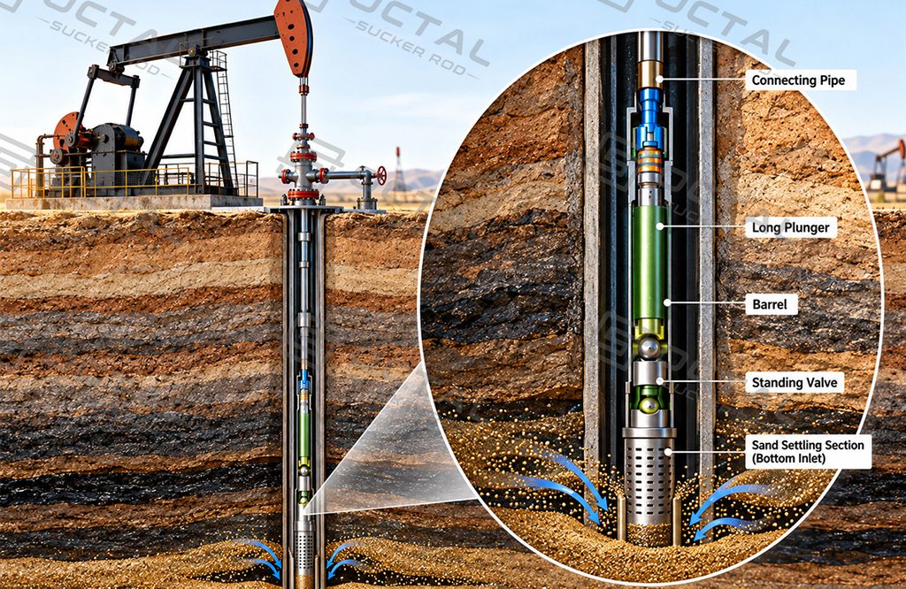
Wells completed in unconsolidated sandstone formations may produce sand together with oil and water.Sand particles entering the pump can accumulate near the plunger, scratch the barrel surface, or become trapped between valve balls and seats.These conditions increase leakage and may eventually cause the plunger to stick.
Long-plunger anti-sand pumps use an extended plunger and short barrel arrangement to reduce sand-related sticking risks.Sand-settling pumps provide an alternative approach by directing particles into a separate settling section instead of allowing them to circulate through the main working area.
The supplied lateral-inlet and bottom-inlet sand-settling configurations are intended for such conditions.
Pump performance still depends on sand concentration, particle size, fluid velocity, and the available settling capacity.
Gas-Prone Oil Wells
In wells with a high gas-oil ratio, free gas may enter the pump chamber along with the produced liquid.Unlike liquid, gas is compressible. During the downstroke, part of the plunger movement compresses the gas rather than transferring liquid through the traveling valve.Severe gas interference can delay valve opening and reduce effective displacement. Under certain conditions, gas lock may prevent normal pumping.
Hollow anti-gas pumps use modified internal flow arrangements to reduce gas-related interference.Forced mechanical valve pumps use a mechanically actuated valve mechanism to improve valve operation under gas-prone conditions.
However, successful gas handling also depends on pump intake pressure, pump submergence, gas separation, and operating speed. Selecting an anti-gas pump does not eliminate the need to evaluate these conditions.
Corrosive Oil Wells
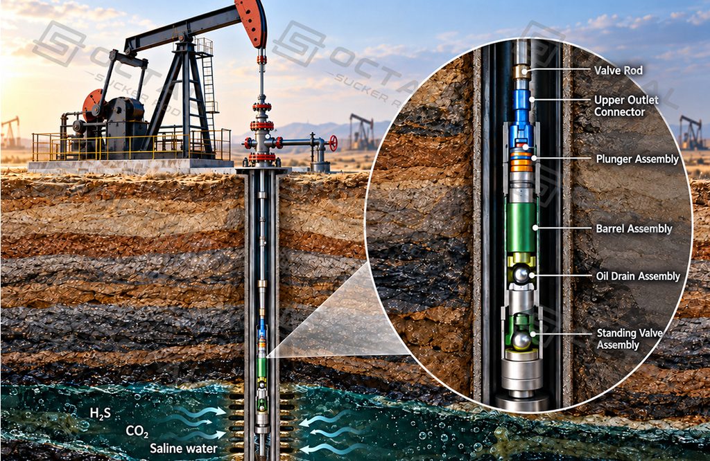
Produced fluids containing H₂S, CO₂, and saline water can accelerate corrosion of the pump barrel, plunger, valves, and connecting components.Corrosion damages sealing surfaces and may increase the clearance between moving parts, allowing more liquid to leak backward during operation.
Anti-wear and anti-corrosion pumps use selected materials, hard-alloy valve components, and treated working surfaces to improve resistance to specific corrosive and abrasive conditions.
The correct material combination must be selected according to produced-water chemistry, operating temperature, H₂S and CO₂ exposure, and the relevant material requirements.For sour-service wells, suitability must be evaluated against the actual environment and applicable NACE MR0175/ISO 15156 requirements rather than assumed from a general corrosion-resistant description.
Deep and Deviated Wells
Deep wells impose greater suspended loads on the sucker rod string, while rod stretch and dynamic effects can reduce effective downhole plunger movement.
In deviated wells, rod-string contact with the production tubing introduces additional friction and wear.These conditions affect pumping efficiency, component service life, and the reliability of pump seating arrangements.
A smaller pump may be preferable in low-production deep wells when available reservoir inflow does not justify a larger displacement capacity.For deviated wells, rod guidance, tubing clearance, connection integrity, and pump alignment require particular attention.
The supplied pump range includes conventional rod-pump and forced mechanical valve configurations intended for selected deep, deviated, or horizontal well applications. Final suitability depends on the specific pump design and complete well operating conditions.
Sucker Rod Pump Technical Reference
Review the technical reference for sucker rod pump specifications, operating principles, specialty pump configurations, and theoretical capacity calculations. The document includes dimensional data, calculation examples, and technical verification notes for further reference.
FAQ
Q: What is the difference between a sucker rod and a sucker rod pump?
A: A sucker rod transmits reciprocating motion from the surface pumping unit to the downhole pump. The sucker rod pump converts this motion into fluid displacement through a plunger, barrel, traveling valve, and standing valve to lift well fluids to the surface.
Q: Can a sucker rod pump handle high-viscosity crude oil?
A: Yes, but high-viscosity crude increases flow resistance and may reduce pump fillage and production efficiency. Pump diameter, valve flow area, stroke length, and pumping speed must be selected according to fluid viscosity, operating temperature, and available reservoir inflow.
Q: How long does a sucker rod pump typically last?
A: Sucker rod pump service life varies with well conditions and operating loads. Sand abrasion, corrosion, valve leakage, and plunger-barrel wear can shorten its service life. Regular production monitoring and inspection help identify performance deterioration and determine when maintenance is necessary.
Q: Does API 11AX compliance mean a sucker rod pump is suitable for H₂S service?
A: No. API 11AX compliance alone does not confirm suitability for sour-service conditions. Materials must be evaluated against actual H₂S exposure, temperature, pressure, and mechanical stresses, with NACE MR0175/ISO 15156 requirements verified where applicable.