
Polished Rod is the smooth-surface steel rod installed at the top of a sucker rod pumping system, connecting the surface pumping unit with the downhole sucker rod string while providing the sealing surface that passes through the stuffing box. It is typically manufactured from carbon steel, alloy steel, or corrosion-resistant steel according to mechanical loading and produced-fluid conditions. During each pumping cycle, the polished rod transfers reciprocating motion and axial load from the surface pumping unit to the downhole pump while moving through the stuffing box to maintain a continuous seal and reduce produced fluid leakage at the wellhead. Polished rods are commonly applied in conventional rod-lift wells, higher-load pumping systems, and oilfield conditions where sealing performance, wear resistance, and corrosion resistance are critical.
Unlike downhole sucker rods that mainly transfer tensile load along the rod string, polished rods operate at the connection point between surface equipment and the complete rod-lift system. Their service performance depends on the combined control of rod diameter, tensile strength, surface finish, straightness, connection geometry, and stuffing-box compatibility. Because the component is subjected to repeated loading cycles and continuous surface contact, proper selection requires consideration of pumping conditions, rod-string load, corrosion environment, and connection matching rather than diameter alone.
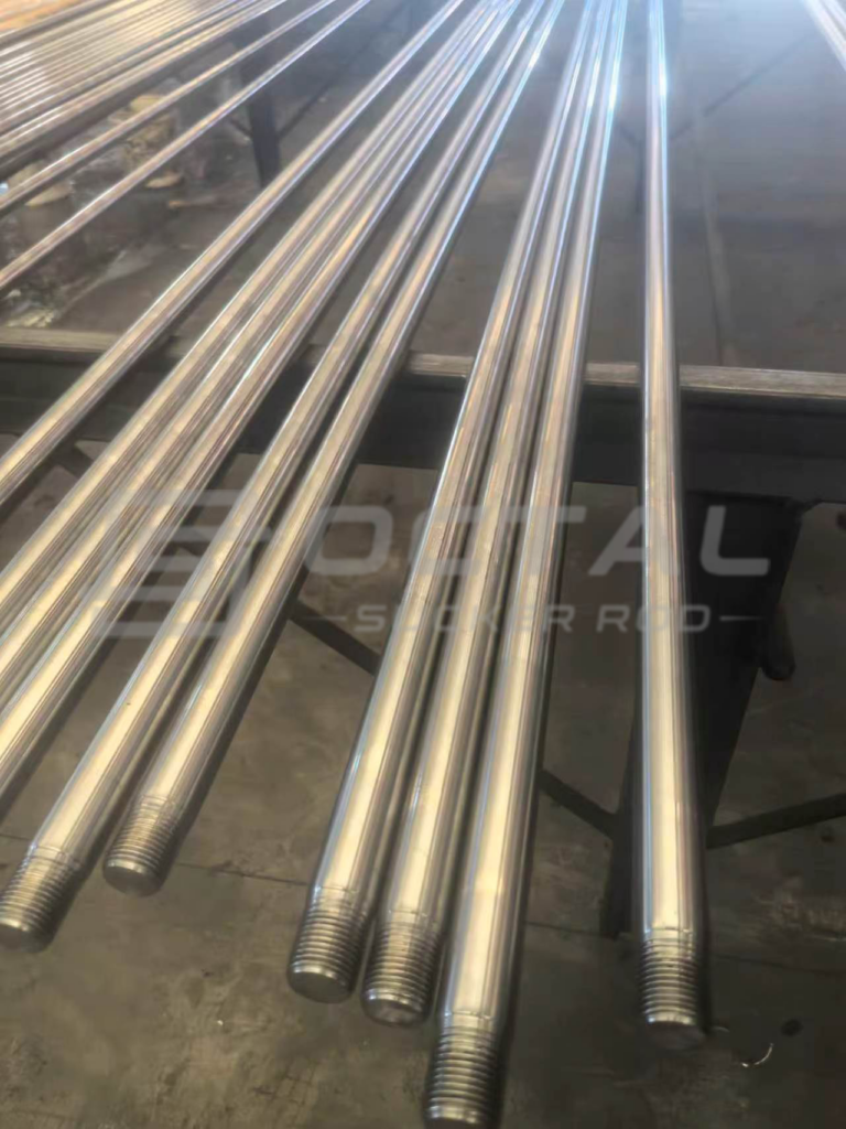
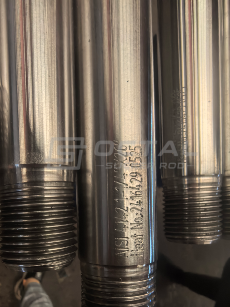
Polished Rod Specifications and Dimensions
An API 11B polished rod is defined by its nominal diameter, working length, material grade, connection design and surface condition. Unlike standard sucker rods, the polished rod must also maintain a controlled sealing surface for continuous movement through the stuffing box.
Key specifications such as diameter, length, material selection and connection compatibility are determined by pumping load, stroke condition, wellhead arrangement and service environment. The working surface quality and dimensional accuracy directly affect sealing performance and operating reliability.
Polished Rod Specification Reference
| Specification Item | Technical Reference |
|---|---|
| Product | Polished Rod |
| Main Application | Surface load transfer and dynamic sealing in sucker rod pumping systems |
| Applicable Standard | API Spec 11B where specified |
| API Nominal Diameters | 1-1/8 in., 1-1/4 in., 1-1/2 in. |
| Additional Industry Configuration | 1-3/4 in. project-based configuration |
| Main Materials | Carbon steel, alloy steel, stainless / corrosion-resistant construction |
| Product Types | Regular, end-upset, spray-metal |
| Working Surface | Precision-finished sealing section |
| End Connection | Polished rod pin connection with compatible polished rod coupling |
| Length | Defined by stroke, wellhead geometry and installation arrangement |
| Main Operating Conditions | Conventional rod lift, higher-load, corrosive, abrasive and long-stroke service |
Polished rod selection should be evaluated as a complete operating component rather than by diameter alone. Rod size, material grade, surface condition, connection design and coupling compatibility must be matched with pumping load, stroke condition, wellhead sealing requirements and service environment to ensure reliable load transfer and stable stuffing-box performance during repeated pumping cycles.
Polished Rod Diameter, Area and Nominal Mass
Polished rod diameter directly affects the steel cross-sectional area, load-bearing capability and nominal weight of the rod body. Larger diameters provide a greater material section for carrying axial load, but they also increase rod weight and may affect coupling clearance, stuffing-box compatibility and overall rod-string design.
The following values represent the approximate straight rod-body section based on steel density. Actual finished weight may vary depending on end upset geometry, connection design and surface treatment.
| Nominal Size | OD | Cross-Sectional Area | Approx. Solid-Steel Mass |
|---|---|---|---|
| 1-1/8 in. | 28.58 mm | 641.5 mm² | 5.04 kg/m |
| 1-1/4 in. | 31.75 mm | 791.7 mm² | 6.22 kg/m |
| 1-1/2 in. | 38.10 mm | 1,140.1 mm² | 8.95 kg/m |
| 1-3/4 in.* | 44.45 mm | 1,551.8 mm² | 12.18 kg/m |
The increase in diameter provides a larger load-carrying section, but polished rod selection cannot be based on diameter alone. Pumping load, stroke condition, stuffing-box requirements, connection design and service environment must also be considered as part of the complete rod-lift system.
Polished Rod Material and Tensile Strength
Material selection determines the mechanical-property range of a polished rod. Carbon steel, alloy steel and stainless steel routes are selected according to required strength, corrosion exposure and operating environment.
| Material Route | Representative Material Family | Finished-Product Tensile Requirement |
|---|---|---|
| Carbon Steel | AISI 1035–1050 | 90–160 ksi / 621–1,103 MPa |
| Alloy Steel | AISI 4120–4140, 4315–4340, 4615–4625, 8620–8630 | 95–160 ksi / 655–1,103 MPa |
| Stainless Steel | 304 / 316 | ≥70 ksi / 482 MPa |
Higher tensile strength does not automatically determine the best polished rod selection. The final configuration must consider mechanical loading, corrosion exposure, surface requirements and compatibility with the surrounding rod-lift system.
Polished Rod Diameter Effect on Nominal Stress
The influence of polished rod diameter becomes more significant when comparing nominal stress under the same axial loading condition. A larger cross-sectional area reduces the average stress level for the same applied force, providing additional mechanical margin during operation.
| Size | Cross-Sectional Area | Stress at 60 kN | Stress at 80 kN | Stress at 100 kN |
|---|---|---|---|---|
| 1-1/8 in. | 641.5 mm² | 93.5 MPa | 124.7 MPa | 155.9 MPa |
| 1-1/4 in. | 791.7 mm² | 75.8 MPa | 101.0 MPa | 126.3 MPa |
| 1-1/2 in. | 1,140.1 mm² | 52.6 MPa | 70.2 MPa | 87.7 MPa |
| 1-3/4 in. | 1,551.8 mm² | 38.7 MPa | 51.6 MPa | 64.4 MPa |
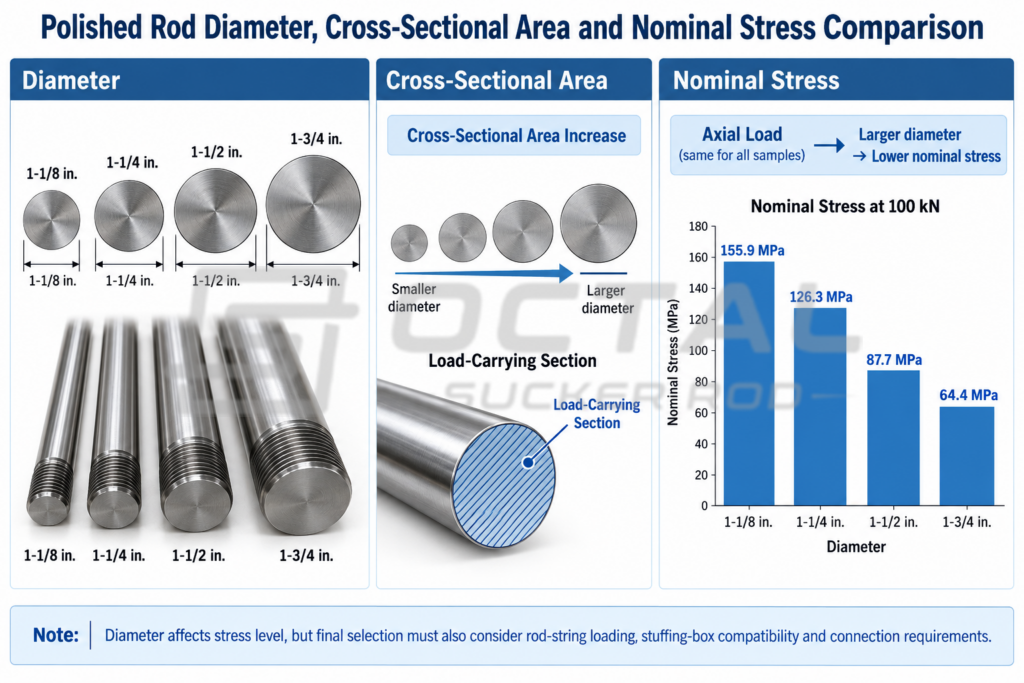
The comparison shows how polished rod diameter affects nominal stress under the same axial load. Larger diameters reduce stress by providing a greater load-bearing section, but final selection must also consider material grade, connection design and operating conditions.
Polished Rod Structure, Load Path and Manufacturing Process
A polished rod is not only a surface connection component between the pumping unit and the downhole rod string, but also a mechanical member that carries repeated axial loading during sucker rod pumping operation. Its design combines a precision-finished working section with a load-bearing rod body and connection structure, allowing the polished rod to transfer surface motion while maintaining reliable sealing through the stuffing box.
The overall performance of a polished rod depends on the relationship between its structural components, load transfer path and manufacturing control. The rod body carries the main axial load, while the forged end, polished rod pin and coupling connection ensure that the applied load is transferred safely into the sucker rod string.
Polished Rod Structural Components
The structure of a polished rod includes several functional areas designed for different mechanical requirements. Unlike a simple solid steel bar, each section has a specific role in load transfer, connection reliability and sealing performance.
| Structural Component | Function |
|---|---|
| Polished Section | Provides the smooth working surface that moves through the stuffing box packing and maintains dynamic sealing |
| Rod Body | Carries the main axial tensile load generated during pumping operation |
| Forged End | Provides increased cross-sectional area for the connection region and supports thread machining |
| Pin Connection | Forms the threaded connection with the polished rod coupling and transfers axial load across the joint |
| Coupling | Connects the polished rod to the adjoining sucker rod string while maintaining mechanical continuity |
The polished section serves as the dynamic sealing interface between the rod and stuffing box packing, requiring controlled surface condition and dimensional accuracy throughout repeated reciprocating movement. The rod body provides the primary axial load-carrying section, while the forged end increases the connection cross-section for the pin, shoulder and thread area. Together, these regions form a continuous mechanical load path from the surface pumping unit to the sucker rod string, with each section designed to maintain load transfer reliability under cyclic pumping conditions.
Load Transfer During Pumping Operation
During sucker rod pumping, the polished rod operates as the upper load-transmitting member of the rod string. The surface pumping unit generates reciprocating movement, and the polished rod transfers this motion and the corresponding axial load through the sucker rod string to the downhole pump.
The loading condition changes continuously during each pumping cycle. During the upstroke, the polished rod mainly experiences tensile loading as the rod string is lifted. During the downstroke, the load direction and stress distribution change as the rod string and pump assembly return downward. Therefore, the polished rod is designed for repeated cyclic loading rather than a single static load condition.
| Operating Stage | Load Behavior | Engineering Consideration |
|---|---|---|
| Upstroke | Tensile loading increases as the rod string is lifted | Requires sufficient rod-body strength and connection reliability |
| Downstroke | Load changes during downward movement and creates cyclic stress variation | Requires fatigue resistance of the rod and connection areas |
| Continuous Pumping Cycle | Repeated loading occurs throughout long-term operation | Requires controlled material properties, geometry and surface condition |
The cyclic loading effect is especially important at the forged transition, pin shoulder and thread area, where geometric changes may increase local stress concentration. For this reason, polished rod manufacturing requires controlled forging, machining and heat treatment to maintain connection integrity during service.
Polished Rod Manufacturing Process
The manufacturing process of a polished rod focuses on controlling the mechanical properties, connection geometry and surface condition required for reliable operation under repeated pumping cycles. The main production stages include end forging, machining, heat treatment and surface finishing, with each stage affecting load transfer capability, connection reliability and sealing performance.
| Manufacturing Stage | Engineering Purpose |
|---|---|
| End Forging | Forms the enlarged end section required for the polished rod pin, shoulder and connection area while maintaining a controlled transition from the rod body |
| Machining | Produces accurate polished diameter, pin geometry and thread profile to ensure proper connection fit and dimensional consistency |
| Heat Treatment | Establishes the required balance of strength, toughness and fatigue resistance for cyclic pumping loads |
| Surface Finishing | Creates the controlled working surface required for stable contact with stuffing box packing and long-term sealing performance |
The manufacturing quality of a polished rod depends on the interaction of these processes rather than on a single operation. Controlled forging reduces stress concentration at the transition area, accurate machining ensures connection compatibility, and surface finishing maintains the sealing performance required during continuous reciprocating movement.
Polished Rod Configurations and Applications
Polished rod configurations differ mainly in end design, surface protection and material selection. The appropriate configuration depends on the combined requirements of rod loading, stuffing-box sealing, corrosion exposure and connection compatibility rather than nominal size alone.
| Configuration | Main Features | Typical Material / Treatment | Suitable Conditions | Main Selection Focus |
|---|---|---|---|---|
| Regular Polished Rod | Standard polished section with conventional end connection design | Carbon steel or alloy steel with precision surface finishing | Conventional rod lift systems and moderate loading conditions | Surface quality, dimensional accuracy and compatibility with stuffing box and sucker rod string |
| End-Upset Polished Rod | Enlarged forged end section providing additional connection-area cross section | Forged end with controlled transition and machined pin connection | Higher rod loading, longer stroke operation or larger pumping systems | Connection strength, forged transition geometry and cyclic load resistance |
| Spray-Metal Polished Rod | Metallic coating applied on the working surface to improve wear resistance | Base steel with spray-metal surface protection | Corrosive produced fluids or abrasive operating environments | Coating integrity, wear resistance and stuffing box compatibility |
| Corrosion-Resistant Polished Rod | Material selection focused on corrosion performance under specific service conditions | Corrosion-resistant material route according to well environment | High chloride, CO₂/H₂S exposure or severe corrosion conditions | Corrosion mechanism, mechanical loading and long-term surface performance |
The selected polished rod configuration should match the complete rod-lift system. Surface condition, connection design and operating environment must be evaluated together to maintain reliable load transfer and sealing performance during repeated pumping cycles.
Polished Rod Position and Working Principle in a Rod-Lift System
Position in the Rod-Lift System
Polished rod is installed at the upper section of a sucker rod pumping system, between the surface pumping unit and the downhole sucker rod string. It connects the surface lifting mechanism with the underground pumping components while passing through the stuffing box to provide a moving sealing surface at the wellhead.
The complete mechanical load path can be described as:
Surface Pumping Unit → Polished Rod Clamp → Polished Rod → Sucker Rod String → Downhole Pump
Each component has a different role in transferring motion and load from the surface equipment to the pump.
| Operating Component | Function in the System |
|---|---|
| Surface Pumping Unit | Generates the reciprocating movement required for pumping |
| Polished Rod Clamp | Transfers surface movement and supports the polished rod connection |
| Polished Rod | Transfers axial load while moving through the stuffing box sealing system |
| Stuffing Box | Maintains dynamic sealing around the moving polished rod surface |
| Sucker Rod String | Transmits movement and load to the downhole pump |
| Downhole Pump | Converts rod movement into fluid lifting action |
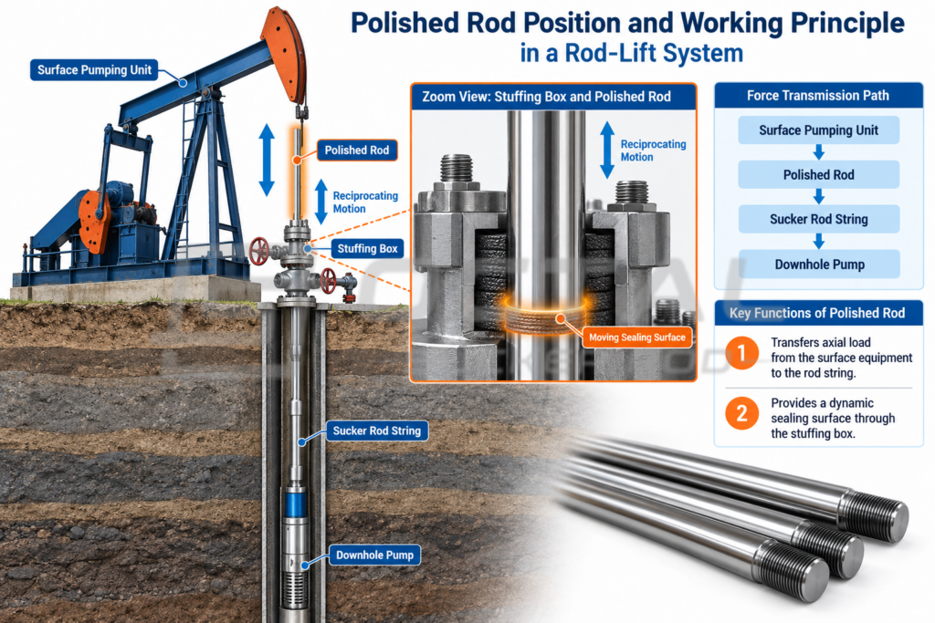
Working Principle During Pumping Cycles
During operation, the polished rod moves vertically together with the surface pumping unit and sucker rod string. The component is subjected to repeated tensile loading rather than a single static load because the rod string continuously accelerates, reverses direction and changes loading condition during each pumping cycle.
During the upstroke, the pumping unit lifts the rod string and the polished rod carries the tensile load generated by the suspended rod weight, fluid load and pump resistance. During the downstroke, the load condition changes as the rod string moves downward, but the polished rod continues to guide movement through the stuffing box while maintaining sealing contact.
Therefore, polished rod performance depends not only on tensile strength, but also on surface finish, straightness, connection alignment and compatibility with the stuffing-box sealing system.
Polished Rod Connection and Coupling Compatibility
The polished rod connection is a critical part of the surface load path because it transfers the reciprocating load from the polished rod into the sucker rod string. The connection performance depends on the combined design of the pin, shoulder, thread profile and coupling, rather than the nominal rod diameter alone.
A properly matched connection maintains mechanical engagement and load distribution during repeated pumping cycles. The following reference summarizes the main polished rod thread and coupling features that affect connection compatibility.
| Connection Feature | Typical Reference | Engineering Function |
|---|---|---|
| Connection Type | Polished rod pin with matching coupling | Transfers axial load between polished rod and sucker rod string |
| Thread Type | Straight thread | Provides mechanical engagement between pin and coupling |
| Thread Frequency | 10 threads per inch | Defines thread engagement and connection fit |
| Pin Thread Profile | UNR with rounded root contour | Improves thread fatigue performance under cyclic loading |
| Box Thread Profile | UN form | Matches the polished rod pin geometry |
| Shoulder Design | Shoulder contact connection | Provides axial load-bearing contact after makeup |
| Vanish Cone | 9° | Controls thread runout and connection geometry |
| Coupling Type | Compatible polished rod coupling | Maintains correct connection envelope and load transfer |
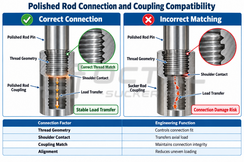
The polished rod connection should be treated as an integrated system consisting of the polished rod pin, polished rod coupling and connected sucker rod string. A coupling with similar dimensions but incompatible thread geometry or shoulder design may result in improper makeup and uneven load transfer.
For replacement or new installations, connection type, coupling compatibility and installed rod-string configuration should be verified together to maintain reliable operation under cyclic loading conditions.
Polished Rod Selection for Different Well Conditions
Polished rod selection should consider the combined effects of mechanical loading, sealing requirements, produced-fluid conditions and installation compatibility. The same polished rod diameter can be supplied with different material and surface configurations, so diameter alone does not determine service suitability. The selection should match the actual rod-string load, stuffing-box condition, corrosion environment and operating requirements.
| Operating Condition | Main Selection Consideration | Recommended Configuration Focus |
|---|---|---|
| Conventional Rod-Lift Well | Normal cyclic loading and stable sealing condition | Standard polished surface, suitable diameter and compatible polished rod coupling |
| Higher Rod-String Load | Increased tensile stress and fatigue demand | Larger load-carrying section, suitable material strength and reliable connection design |
| Long-Stroke Operation | Increased sliding distance and packing contact cycles | Surface finish quality, straightness control and wear resistance |
| Corrosive Produced Fluid | Corrosion attack on rod surface and sealing area | Corrosion-resistant material or protected surface construction |
| Abrasive / Scale-Bearing Fluid | Surface scoring and accelerated packing wear | Wear-resistant surface and proper stuffing-box compatibility |
| Replacement Service | Existing system matching requirements | Correct diameter, length, connection type and coupling compatibility |
The correct polished rod configuration is determined by the complete operating system rather than a single parameter. Mechanical strength, surface condition, connection matching and well environment should be evaluated together to maintain reliable load transfer and sealing performance during repeated pumping cycles.
Polished Rod Supply and Technical Support
Octal supplies polished rods for sucker rod pumping systems, with configurations covering different rod sizes, materials, surface constructions and connection requirements. Each polished rod can be coordinated with related rod-string components, including sucker rods and couplings, to maintain compatibility within the complete pumping system.
Technical support includes specification review, material confirmation, connection matching, dimensional inspection and production documentation. Based on the project requirements, Octal can provide traceable records covering material identification, mechanical properties, inspection results and product marking to support reliable installation and field operation.
FAQ
What is the difference between a polished rod and a sucker rod?
A polished rod and a sucker rod have different positions and functions in a rod-lift system. The polished rod is installed at the surface end of the rod string and provides both axial load transfer and a continuous sealing surface through the stuffing box. The sucker rod string mainly transfers reciprocating load between the surface equipment and the downhole pump. Therefore, polished rod selection requires additional consideration of surface finish, straightness and stuffing-box compatibility.
How do you select the correct polished rod size?
Polished rod size should be selected according to the complete rod-lift system rather than diameter alone. The main factors include rod-string loading, pumping unit capacity, stuffing-box requirements, connection compatibility and operating environment. A larger diameter provides a greater load-carrying section, but the final selection must also consider installation clearance and sealing performance.
Why is polished rod surface finish important?
The surface finish of a polished rod directly affects stuffing-box sealing performance because the rod repeatedly moves through the packing during each pumping cycle. Surface roughness, straightness and surface defects can influence friction, leakage and packing wear. Therefore, polished rod quality depends not only on mechanical strength but also on the condition of the working sealing surface.
Can a sucker rod coupling be used with a polished rod?
A standard sucker rod coupling should not be selected only by nominal size for polished rod applications. The polished rod connection requires a compatible coupling design to match the pin geometry, thread configuration and load-transfer requirements. Using an incompatible coupling may affect makeup condition, connection integrity and long-term fatigue performance.