
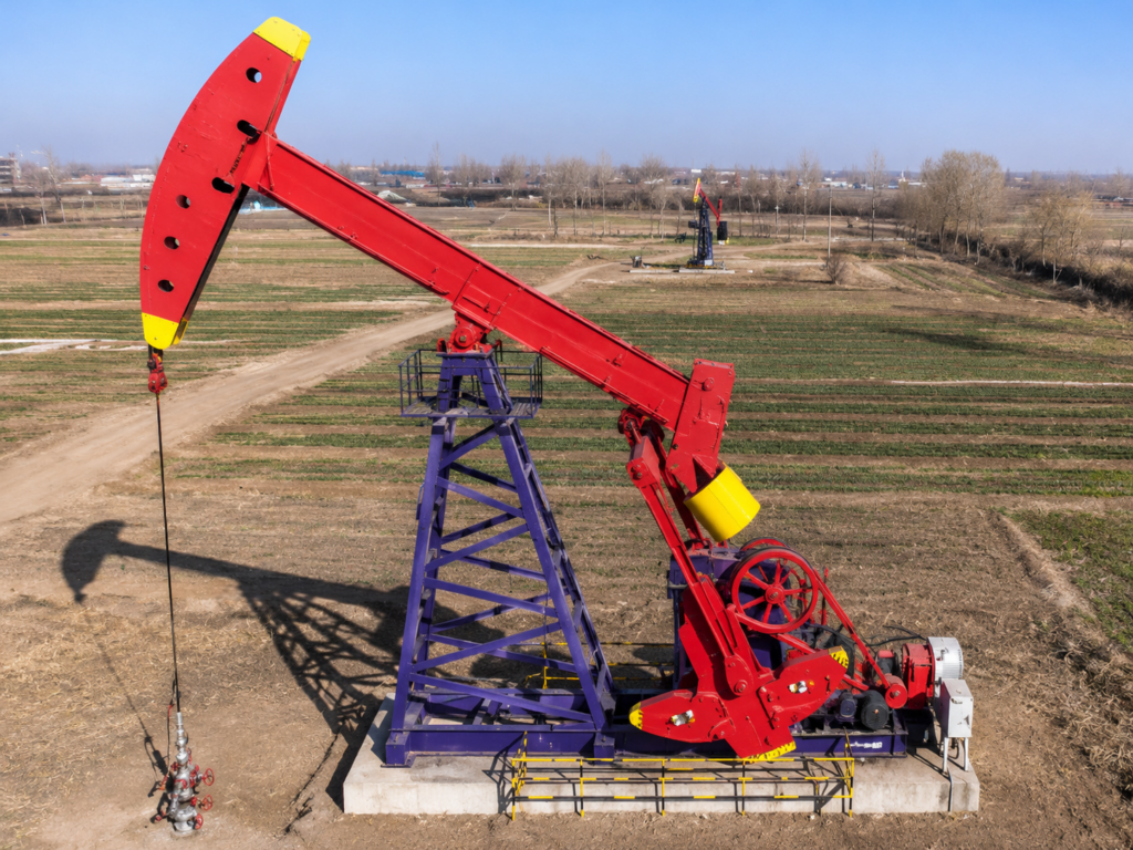
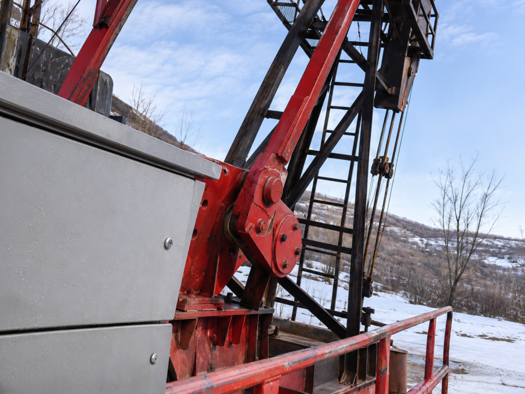
IoT Oil Field Monitoring System brings together intelligent sensing, data acquisition, and wireless communication technologies to support oilfield production monitoring and equipment management. It connects oil and gas wells, water wells, pumping units, sucker rods, progressive cavity pumps, and other production equipment through a centralized digital management platform. Designed for oilfields with multiple distributed wells, the system enables centralized monitoring and management of production operations and equipment information.
Combining specialized software modules with field monitoring devices, the system supports rod string design, rod-pumped and progressive cavity pump management, intelligent pumping-unit control, liquid-level measurement, dynamometer data acquisition, and RFID-based equipment tracking. It integrates well information, equipment configurations, operating data, and maintenance records, enabling equipment tracking throughout its lifecycle, from manufacturing and installation to operation and maintenance. With online monitoring and management capacity for 20,000 oil wells, the system helps improve production visibility, support equipment condition analysis, facilitate maintenance planning, and enhance the efficiency of oilfield operations.
System Architecture and Software Modules
The IoT Oil Field Monitoring System connects three main components: a centralized software platform, field data acquisition and communication devices, and oil production equipment. The software platform processes and manages information, field devices collect and transmit operating data, and connected equipment provides the production data and operating conditions monitored by the system.
System Architecture
These components are organized into three functional layers:
| System Layer | Main Components | Primary Functions |
|---|---|---|
| Field Equipment | Oil and gas wells, water wells, pumping units, sucker rods, pumps, and related production equipment | Perform production operations and provide equipment information |
| Data Acquisition and Communication | Sensors, dynamometer devices, intelligent control terminals, RFID chips, and communication modules | Collect, identify, and transmit field data |
| Software Management Platform | Engineering calculation, production monitoring, equipment management, historical records, and fault warning modules | Process, display, analyze, and manage production and equipment information |
Software Modules
| Software Module | Main Function |
|---|---|
| Rod-Pumped Oil Production Module | Monitoring and management of rod-pumped production equipment |
| Progressive Cavity Pump Module | PCP selection, operating data monitoring, and equipment management |
| Rodless Pump Production Module | Management functions for rodless pumping equipment |
| IoT Chip Issuing and Query Module | RFID chip registration, identification, and information retrieval |
| System Configuration Module | System-level configuration and management |
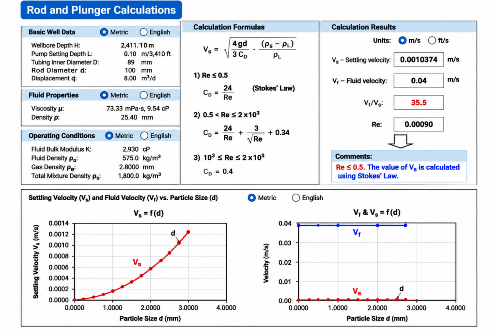
| Rod String Design Module | Rod and plunger combination design, verification, and engineering calculations |
Data Integration and Management
The platform organizes available records into three main categories:
- Well and equipment information: Wellhead data, rod and plunger configurations, and associated production equipment records.
- Operating and measurement data: Pumping equipment operating data, liquid-level measurements, dynamometer cards, and power-related information.
- Historical and identification records: Equipment operating history, fault records, and RFID-based equipment identification information.
The available information depends on the installed field devices and configured software modules. By bringing these records together, operators can review equipment configurations alongside operating conditions and historical data, supporting production monitoring, equipment assessment, and maintenance planning.
Rod String Design Module
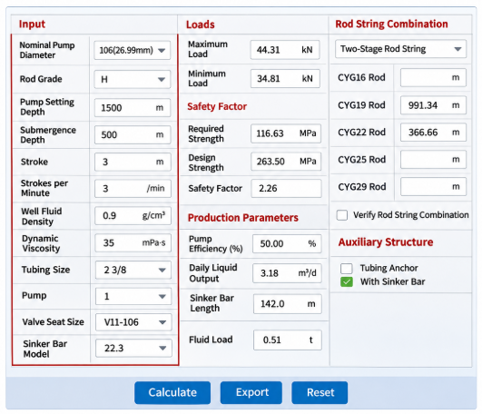
The Rod String Design Module provides engineering calculations for sucker rod and plunger combinations based on well conditions and pumping parameters. It supports rod string selection and design by evaluating maximum and minimum loads, allowable stress, design strength, and safety factors.
The module also supports verification of existing rod string configurations and centralizer rod design. These functions help engineers assess rod string suitability under actual operating conditions and manage rod-to-tubing contact, particularly in deviated wells where eccentric wear may occur.
Rod-Pumped Oil Production Function Module
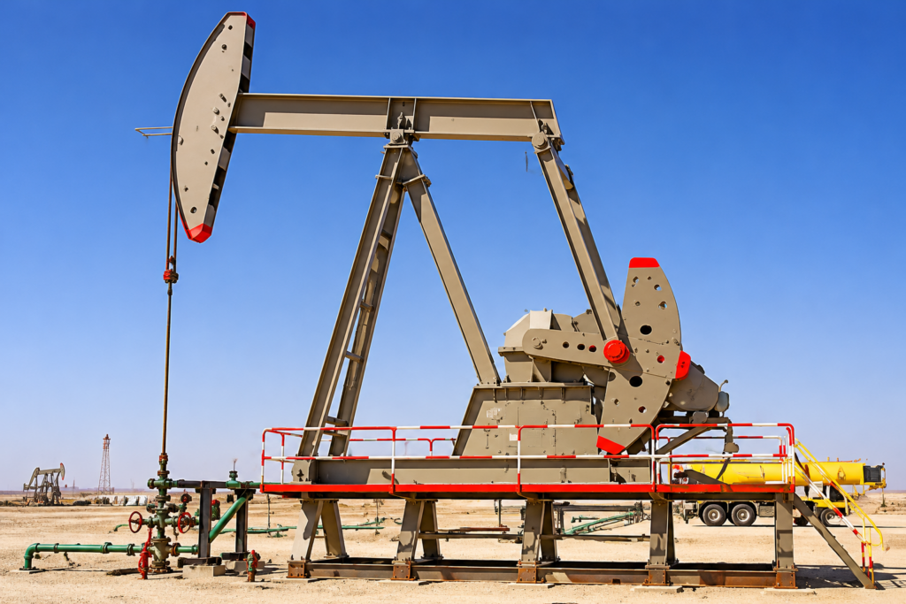
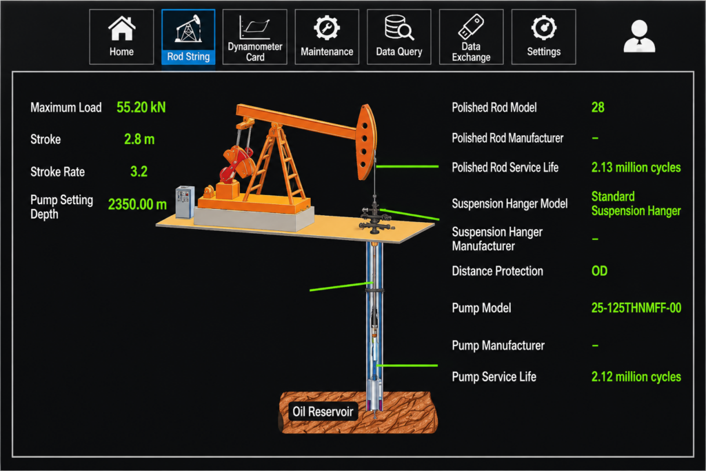
The Rod-Pumped Oil Production Function Module focuses on the operating management of sucker rod pumping systems. It integrates production equipment monitoring, well information management, historical data queries, and fault warning functions. By collecting operating data from pumping units and related equipment, the system helps operators review well conditions, evaluate pumping performance, and identify abnormal operating conditions.
The main functions are organized into four areas:
| Functional Category | Main Functions and Applications |
|---|---|
| Oil Production Equipment Monitoring | Monitors pumping equipment operation, well liquid levels, dynamometer cards, and electrical power data. Data curve displays provide a visual reference for reviewing equipment performance, while video surveillance supports remote wellsite monitoring. |
| Well Information and Historical Data | Manages wellhead information, rod and plunger configurations, and associated production equipment records, including polished rods, sucker rods, and pumps. Operation history and fault history functions allow users to review previous equipment conditions and events. |
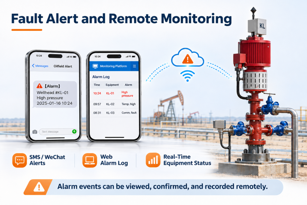
| Fault Warning and Wellsite Video Surveillance | Provides operational threshold alarms, oil production equipment service-life warnings, dynamometer card fault warnings, and alerts for external vehicles and personnel at the wellsite. Electronic wellsite cameras support remote inspection and safety checks. |
| Alarm Notifications and Production Data Analysis | Supports SMS alerts and remote access through mobile devices, allowing operators to review alarm notifications, event details, and equipment status. A model library combining oilfield production experience and technical knowledge with a real-time database supports production data analysis, fault diagnosis, and early warning. |
For rod-pumped wells, dynamometer card monitoring is particularly important. The card shows the relationship between polished rod load and displacement during a pumping cycle. Together with liquid-level measurements and power data, it provides additional information for evaluating pumping conditions and identifying potential operating abnormalities.
When an alarm occurs, operators can review the recorded event, manually confirm the alarm, and retain the information for subsequent analysis. These functions support equipment condition monitoring, fault investigation, and maintenance planning throughout daily oilfield production.
Progressive Cavity Pump (PCP) Function Module
The Progressive Cavity Pump (PCP) Function Module provides engineering support for screw-pump selection and production equipment management. Its main engineering functions include selecting progressive cavity pumps and their drives according to well conditions and calculating wellhead characteristic curves. The module also integrates equipment monitoring, well information management, historical data queries, and fault warning functions.
The main functions are organized into the following categories:
| Functional Category | Main Functions and Applications |
|---|---|
| PCP and Drive Selection | Supports the design and selection of progressive cavity pumps and their associated drives according to well conditions and production requirements. |
| Wellhead Characteristic Curve Calculation | Derives wellhead characteristic curves for the selected pump and drive configuration, providing an engineering reference for evaluating equipment selection. |
| Rod and Plunger Calculation | Includes rod and plunger combination design, combination verification, and centralizer rod design. Detailed engineering functions are covered in the separate Rod String Design Module section. |
| Equipment Monitoring | Monitors equipment operating data, well liquid levels, and electrical power data. Data curve displays and video surveillance provide additional information for reviewing operating conditions. |
| Well Information and Historical Records | Manages wellhead information, rod and plunger details, and other oil production equipment records. Operators can query equipment operation history and fault history. |
| Fault Warning and Alarm Notifications | Provides operational threshold alarms, equipment service-life warnings, and alerts for external vehicles and personnel. Alarm information can be sent through SMS and accessed remotely using mobile devices. |
| Production Data Analysis | Combines oilfield production experience and technical knowledge with a model library and real-time database to support production data analysis and early warning. |
For progressive cavity pump applications, pump and drive selection and wellhead characteristic curve calculation are the key engineering functions. They help engineers evaluate the selected equipment configuration according to actual well conditions. The monitoring and historical data functions provide additional information for reviewing equipment operation, identifying abnormal conditions, and planning maintenance.
IoT Chip Module
The IoT Chip Module uses RFID identification technology to link physical oil production equipment with its digital records. Each registered chip is associated with the corresponding equipment information in the management system, allowing users to identify equipment, retrieve its records, and track installation and removal history. This provides a basis for equipment identification, information management, and lifecycle traceability.
The module covers four main functions:
| Functional Category | Main Functions and Applications |
|---|---|
| Well and Equipment Information Management | Maintains wellhead information, rod and plunger combinations, and records of production equipment such as polished rods, sucker rods, and pumps. Equipment records are associated with individual wells for easier identification and retrieval. |
| RFID Chip Registration and Identification | Supports issuing and registering new RFID chips and linking chip identification information with corresponding equipment records. Users can retrieve the associated digital information through the management system. |
| Downhole and Pull-Out History Records | Maintains records of equipment entering and leaving the well. For components such as sucker rods and tubing, these records help track installation, retrieval, replacement, and maintenance history. |
| Data Dictionary Management | Organizes the information fields used by the software platform to maintain structured and consistent well and equipment records. |
By linking RFID chip identification with well and equipment records, the system connects physical production components with their digital information throughout their service life. This helps operators review equipment specifications, usage history, installation and retrieval records, and maintenance information without relying solely on separate manual records.
Intelligent Control Terminal Module
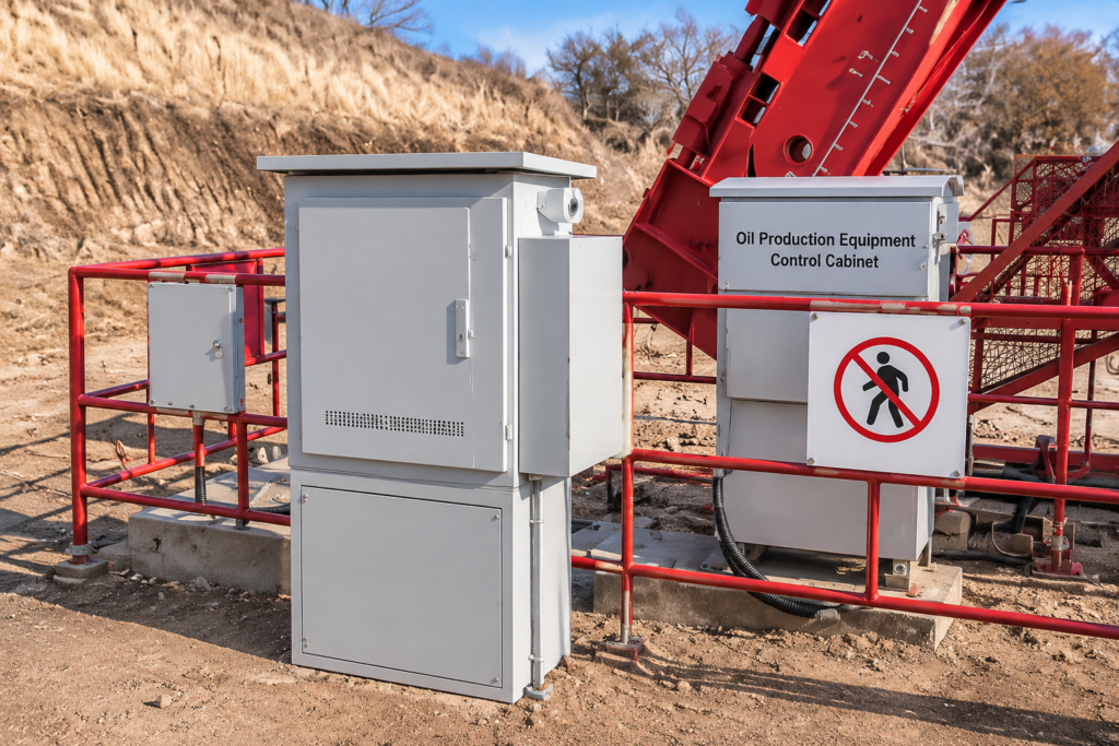
The Intelligent Control Terminal Module connects individual oil production equipment with the system’s data acquisition, monitoring, and control functions. It collects operating parameters, maintains equipment records, and supports intelligent adjustments to compatible pumping units. Its main functions cover three areas:
| Main Function | Technical Functions and Applications |
|---|---|
| Operating Data Acquisition | Collects the number of reciprocating cycles, equipment working loads, motor current and torque changes, and dynamometer data. These records help operators review pumping-unit operating conditions. |
| Equipment Service-Life Management | Stores and processes equipment operating information to support service-life estimation, maintenance planning, and equipment-related warnings. With remote communication modules, warning messages can be transmitted to relevant personnel. |
| Intelligent Pumping Unit Control | Uses dynamometer card information to adjust motor torque and pumping stroke rate, optimizing the operating speed distribution during the stroke cycle. |
Automatic Control and Operating Optimization
For single-well pumping units equipped with a variable frequency drive (VFD) and a dynamometer, the intelligent control system can automatically adjust motor torque according to dynamometer card information. By optimizing the speed distribution of the suspension point throughout the pumping cycle, the system is designed to reduce peak loads and load fluctuations, helping improve pumping efficiency and reduce unnecessary energy consumption.
Acoustic Liquid Level Tester
The Acoustic Liquid Level Tester is a wellhead measurement instrument used to determine the depth of the liquid level in oil wells. It operates by generating an acoustic pulse in the annular space between the casing and tubing and receiving the reflected signals from downhole interfaces. The instrument converts these acoustic signals into electrical signals for processing, allowing the system to identify the gas-liquid interface and determine the well’s liquid-level depth. Depending on well pressure conditions, the acoustic pulse can be generated using casing gas or an external high-pressure gas source.
Main Components and Functions
The instrument assembly includes the following components:
| No. | Component | Function |
|---|---|---|
| 1 | Wellhead Connector | Connects the tester to the wellhead |
| 2 | Venting Valve | Provides the designated gas venting connection |
| 3 | Wellhead Connector Locking Nut | Secures the wellhead connection |
| 4 | Antenna | Supports wireless communication |
| 5 | Silencer | Reduces noise during gas release |
| 6 | Power Cable Inlet | Provides the power connection |
| 7 | Explosion-Proof Junction Box | Houses the designated electrical connections |
The tester receives reflected acoustic signals through its microphone assembly and processes them electronically to obtain liquid-level measurements. Because acoustic conditions vary between wells, the instrument uses well-specific acoustic information to support measurement accuracy.
Split-Type Dynamometer
The Split-Type Dynamometer is a measurement system designed to collect dynamometer card data from beam pumping units. It consists of a load sensor, a dynamometer card acquisition host, a wireless receiver, and a connecting cable. The load sensor measures the polished rod load, while the acquisition host processes the collected signals to generate dynamometer card data. Through an RS-485 interface, the system can transmit load, displacement, stroke, and upper and lower dead-point signals to the monitoring platform for viewing and analysis.
Its split configuration separates the load sensor from the main acquisition unit, providing flexibility in field installation. The acquisition host features an integrated solar power supply, while wireless communication between the host and receiver reduces the need for direct communication cabling. This arrangement supports remote dynamometer data acquisition and transmission, allowing operators to review pumping-unit operating conditions without relying entirely on manual measurements.
All-in-One Wireless Dynamometer
The All-in-One Wireless Dynamometer is a compact digital measurement device designed for dynamometer testing on beam pumping units. It integrates load and displacement sensing, data acquisition, and wireless communication into a single unit. Using MEMS motion detection and force-sensitive sensing technologies, the device measures polished rod load and displacement during pumping operation and wirelessly transmits the collected data to the monitoring system for dynamometer card generation and analysis.
The integrated design simplifies field installation by reducing external wiring and eliminating the need for a separate wired analog signal transmission arrangement. Powered by a solar energy system, the device also features low-power operation, sleep mode, and automatic wake-up. Scheduled data acquisition allows dynamometer cards to be collected at configured intervals during normal pumping operation, without requiring the pumping unit to stop for each measurement. Its compact structure also allows installation without dismantling the polished rod suspension hanger, reducing installation work and improving field measurement convenience.
Oil Production Equipment with RFID Chips
RFID chips are integrated into dedicated protective plugs and threaded caps for oil production equipment identification and information tracking. For sucker rods and polished rods, the chips are housed inside nylon threaded protective plugs and sealed with epoxy resin adhesive. For tubing and sucker rod pumps, the chips are installed inside specially designed pipe-thread protective caps, also protected by epoxy resin encapsulation. These structures protect the chips while connecting individual equipment components with their digital records in the IoT Oil Field Monitoring System.
| Equipment | RFID Chip Installation Structure | Main Functions |
|---|---|---|
| Sucker Rods and Polished Rods | Nylon threaded protective plug with an epoxy-encapsulated RFID chip | Equipment identification, manufacturing information retrieval, quality tracking, service-life warnings, and maintenance-cycle management. |
| Tubing | Pipe-thread protective cap with an epoxy-encapsulated RFID chip | Equipment identification, specification tracking, quality inspection, maintenance warnings, and screening of new and used tubing. |
| Sucker Rod Pumps | Dedicated pipe-thread protective cap with an epoxy-encapsulated RFID chip | Connects pump components with their equipment identification and management records. |
The integration of RFID identification, equipment information management, and intelligent monitoring connects individual production components with the wider oilfield management platform. Combined with well monitoring, data acquisition, and equipment control functions, these technologies provide an integrated approach to managing distributed oil production operations. The following section outlines the main applications of the IoT Oil Field Monitoring System in oilfield production.
System Configuration and Integration
The configuration of an IoT Oil Field Monitoring System should be determined by the production equipment, well conditions, monitoring objectives, and communication infrastructure of each oilfield. Different projects may require different combinations of software modules, monitoring instruments, intelligent control terminals, and RFID identification devices.
OCTAL provides project-oriented system configuration support, helping customers identify the required modules and field devices according to their artificial lift systems, well monitoring requirements, and equipment management needs. The main factors considered during system configuration include:
| Configuration Factor | Project Information to Confirm |
|---|---|
| Production Equipment | Rod-pumping units, progressive cavity pumps (PCPs), rodless pumping equipment, and related production components |
| Well Information | Number of wells, well conditions, and existing production equipment configurations |
| Monitoring Requirements | Dynamometer cards, liquid-level measurements, power data, operating records, and wellsite video surveillance |
| Control Requirements | Whether automatic pumping-unit control is required, including the availability of compatible inverters and dynamometer devices |
| Communication | Available wired and wireless communication interfaces and field communication conditions |
| RFID Management | Equipment requiring RFID chip installation, identification, and lifecycle information management |
Based on these project requirements, OCTAL can help customers determine a suitable combination of software functions and field monitoring devices, supporting the integration of production monitoring, equipment identification, and intelligent control within one management platform. This approach allows the system configuration to match the actual operating conditions and management requirements of each oilfield.
FAQ
Q:How many oil wells can an IoT Oil Field Monitoring System manage?
A:The IoT Oil Field Monitoring System supports online monitoring and management of 20,000 oil wells. It consolidates well information, equipment configurations, operating data, alarms, and historical records into a centralized management platform for distributed oilfield operations.
Q:How does the system support both rod-pumped and progressive cavity pump wells?
A:The system provides separate functional modules for each artificial lift method. Rod-pumped well management covers dynamometer data, liquid-level monitoring, power information, and equipment history, while the PCP module supports pump and drive selection, wellhead characteristic curve calculations, and operating condition monitoring.
Q:Can an IoT oil field monitoring system automatically control pumping units?
A:Yes. When equipped with a compatible variable frequency drive and dynamometer, the intelligent control terminal can use dynamometer card information to adjust motor torque and pumping stroke rate, helping manage suspension-point loads and pumping-unit operation.
Q:How does RFID chip tracking work for oilfield production equipment?
A:RFID chips are installed in protective structures on sucker rods, polished rods, tubing, sucker rod pumps, and polished rod sealing devices. Each chip is associated with equipment records, including specifications, manufacturer, length, maximum load, and usage count, allowing operators to retrieve equipment information and track its service history.