
Sucker rod pump lifts oil from producing wells through production tubing by using reciprocating motion transmitted from a surface pumping unit through a sucker rod string. Designed for conventional and deep wells, deviated wells, and wells producing sand, corrosive fluids or high gas volumes, these downhole pumps use different plunger, barrel and valve configurations to address specific operating conditions, including abrasive wear, corrosion, sand accumulation and gas interference.
OCTAL supplies a range of sucker rod pumps, including wear-resistant and corrosion-resistant tubing and rod pumps, long-plunger anti-sand-sticking and sand-settling pumps, hollow anti-gas pumps, and pumps with forced mechanical valves. Depending on the model, material and surface treatment options include special stainless steel valve cages, hard-alloy valves, nickel-carbon compound barrel plating, Ni60-coated plungers and tungsten-alloy-coated valve rods to improve resistance to wear, corrosion, sand accumulation and gas interference.
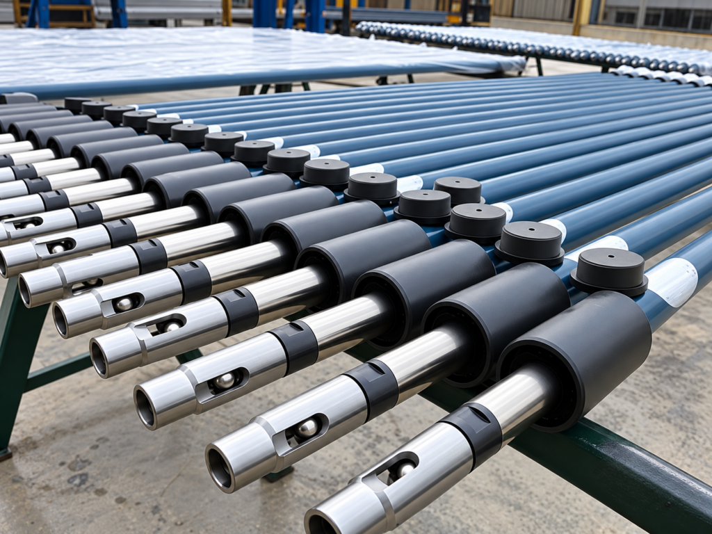
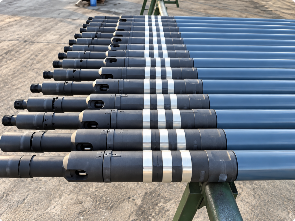
Wear-Resistant and Corrosion-Resistant Sucker Rod Pumps
In wells exposed to corrosive fluids, abrasive wear and demanding pumping cycles, the choice of pump structure and materials affects service life, operating reliability and maintenance requirements. The tubing pump uses a reinforced full-length barrel and a guided traveling-valve cage with a large-flow passage to improve valve movement and resist mechanical stress. Its valve cage can be made from special stainless steel, while hard-alloy valves and sealed plunger threads help address corrosion under demanding well conditions. The rod pump features an insert-type design with top- or bottom-stationary anchoring options, allowing the pump to be retrieved by lifting the sucker rod string without routinely pulling the production tubing. Depending on the model, wear- and corrosion-resistant features include nickel-carbon-compound barrel plating, Ni60-coated plungers, stainless steel valve cages, hard-alloy valves and tungsten-alloy-coated valve rods. The key difference lies in installation and retrieval: the tubing pump forms part of the tubing assembly, whereas the rod pump can be retrieved through the tubing. Selection depends on the well’s corrosive environment, deviation, sand production, completion configuration and maintenance requirements.
Anti-Wear and Anti-Corrosion Tubing Pump
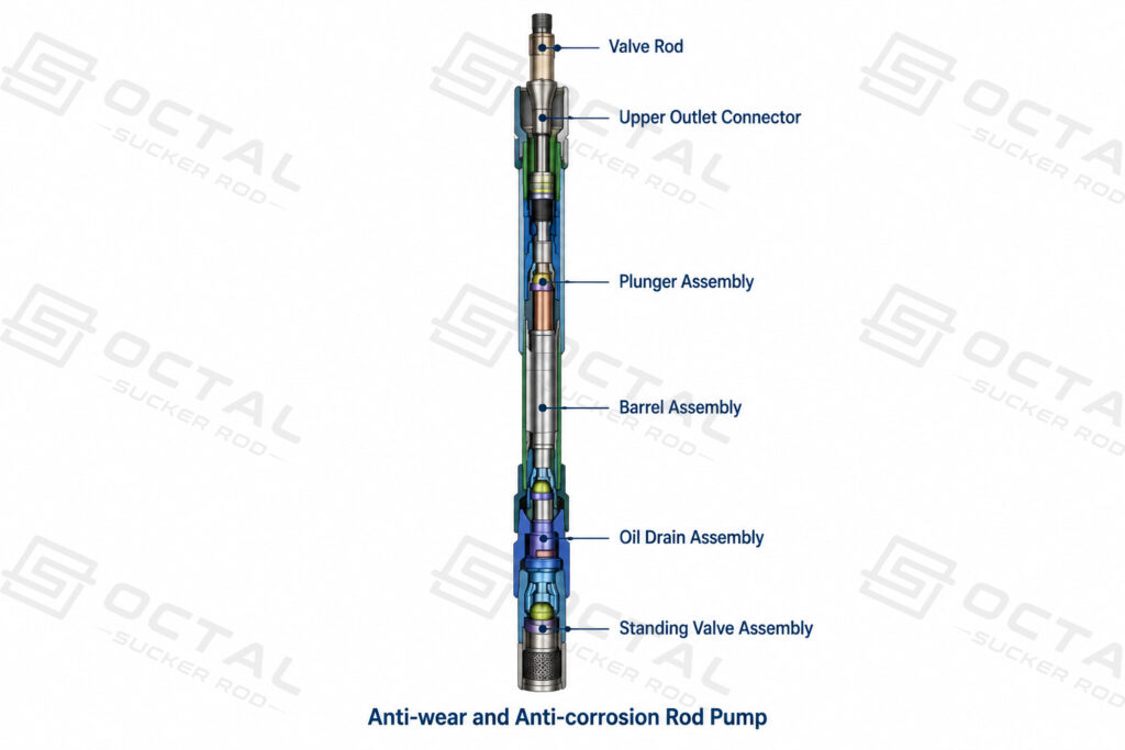
The anti-wear and anti-corrosion tubing pump features a reinforced full-length barrel and a guided traveling-valve cage with a split, large-flow passage. The guide structure helps the valve ball return to its seat, supporting reliable valve movement during repeated pumping cycles, while the reinforced barrel improves mechanical strength and resistance to bending. Depending on the well conditions, the valve cage can be manufactured from special stainless steel, and hard-alloy valve components can be selected to improve resistance to wear and corrosion. A sealing ring at the plunger connection helps protect the threaded connection from corrosive fluids, and an optional oil-drain assembly can help reduce fluid discharge during certain operating and retrieval procedures.
This pump is intended for oil wells producing corrosive fluids containing H₂S, CO₂ or salt water, as well as deviated wells with an inclination of up to 40°. Selection should account for fluid composition, operating temperature and pressure, material compatibility and well geometry. For wells containing H₂S, the selected materials and configuration should also be verified against the applicable sour-service requirements.
Specifications
| Catalog model reference | Nominal diameter covered |
|---|---|
| API designation: 25-(112–225)TH; GB designation: CYB28TH–57.15TH | 28, 31.75, 38.1, 44.45 and 57.15 mm |
| API designation: 30–275TH; GB designation: CYB69.85TH | 69.85 mm |
| API designation: 35–325TH; GB designation: CYB82.55TH | 82.55 mm |
| API designation: 40–375TH; GB designation: CYB95.25TH | 95.25 mm |
| Parameter | 28 mm | 31.75 mm | 38.1 mm | 44.45 mm | 57.15 mm | 69.85 mm | 82.55 mm | 95.25 mm |
|---|---|---|---|---|---|---|---|---|
| Plunger length (mm) | 1,200 | 1,200 | 1,200 | 1,200 | 1,200 | 1,200 | 1,200 | 1,200 |
| Barrel length (mm) | 3,000–12,000 | 3,000–12,000 | 3,000–12,000 | 3,000–12,000 | 3,000–12,000 | 3,000–12,000 | 3,000–12,000 | 3,000–12,000 |
| Upper tubing connection | 2 7/8 in NU | 2 7/8 in NU | 2 7/8 in NU | 2 7/8 in NU | 2 7/8 in NU | 3 1/2 in NU | 4 in NU | 4 1/2 in NU |
| Lower tubing connection | 2 7/8 in NU | 2 7/8 in NU | 2 7/8 in NU | 2 7/8 in NU | 2 7/8 in NU | 2 7/8 in NU | 3 1/2 in NU | 3 1/2 in NU |
| Sucker rod thread | 3/4 in | 3/4 in | 3/4 in | 3/4 in | 3/4 in | 7/8 in | 1 in | 1 in |
| Pump constant (m³/d) | 0.88 | 1.14 | 1.64 | 2.24 | 3.69 | 5.5 | 7.79 | 10.2 |
| Maximum OD (mm) | 88.9 | 88.9 | 88.9 | 88.9 | 88.9 | 108 | 114 | 132 |
Anti-Wear and Anti-Corrosion Rod Pump
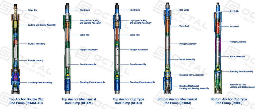
The anti-wear and anti-corrosion rod pump features an insert-type design connected to the sucker rod string, allowing retrieval for inspection or maintenance without routinely pulling the entire production tubing string when the well completion supports this method. Depending on the installation requirements, available configurations include top stationary-anchor models RHAMAC, RHAM and RHAC, and bottom stationary-anchor models RHBM and RHBC. The barrel and plunger arrangement incorporates a grit-arresting feature near the upper barrel to help limit sand deposition when the plunger reaches the lower end of its stroke or pumping stops.
To withstand abrasive particles and corrosive well fluids, the pump can be configured with nickel-carbon-compound barrel plating, Ni60 spray-coated plungers, a special stainless-steel valve cage, hard-alloy valve components and a tungsten-alloy-coated valve rod. These material and surface-treatment options help improve wear resistance and service life under demanding downhole conditions. The pump is suitable for low-liquid-level, low-production deep wells and deviated wells where liquid supply is sufficient and sand or wax accumulation is not severe. For the described application, the pump setting depth should not exceed 3,100 m; the applicable limit must be confirmed for the selected model and well conditions.
Specifications
| Parameter | Catalog specification |
|---|---|
| Nominal pump diameter | 28, 31.75, 38.1, 44.45 and 57.15 mm |
| Stroke length | 1.8–10.0 m |
| Working temperature | Below 100°C |
| Clearance code | I, II and III |
| Plunger length | 1,200 mm |
| Barrel length | 3,000–12,000 mm |
| Parameter | 28 mm | 31.75 mm | 38.1 mm | 44.45 mm | 57.15 mm |
|---|---|---|---|---|---|
| Catalog pump constant (m³/d) | 0.89 | 1.14 | 1.64 | 2.24 | 3.69 |
| Upper and lower tubing connection thread | 2 3/8 in NU/EU | 2 7/8 in NU/EU | 2 7/8 in NU/EU | 2 7/8 in NU/EU | 3 1/2 in NU/EU |
| Sucker rod thread | 5/8 in | 3/4 in | 3/4 in | 3/4 in | 3/4 in |
Anti-Sand and Anti-Scale Sucker Rod Pumps
In wells affected by sand production, scale deposition and related sticking problems, pump structure has a direct influence on operating stability, inspection interval and pump service life. The anti-sand and anti-scale sucker rod pump range is designed for these downhole conditions by using configurations that limit sand entry into critical working areas and improve solids handling during pumping and shutdown. The long-plunger anti-sand-sticking pump uses a long plunger with a short barrel so that the plunger and barrel remain closely matched during operation, helping reduce sand intrusion, plunger sticking and wear caused by accumulated solids. The long-plunger sand-settling pump adds a dedicated settling passage to separate sand movement from the main fluid flow path, and is available in lateral-inlet and bottom-inlet designs to suit different well conditions and solids behavior. Selection between these designs depends on sand content, fluid characteristics, well deviation, completion configuration and the need to control sticking, abrasion and solids deposition in the pump.
Long-Plunger Anti-Sand-Sticking Sucker Rod Pump
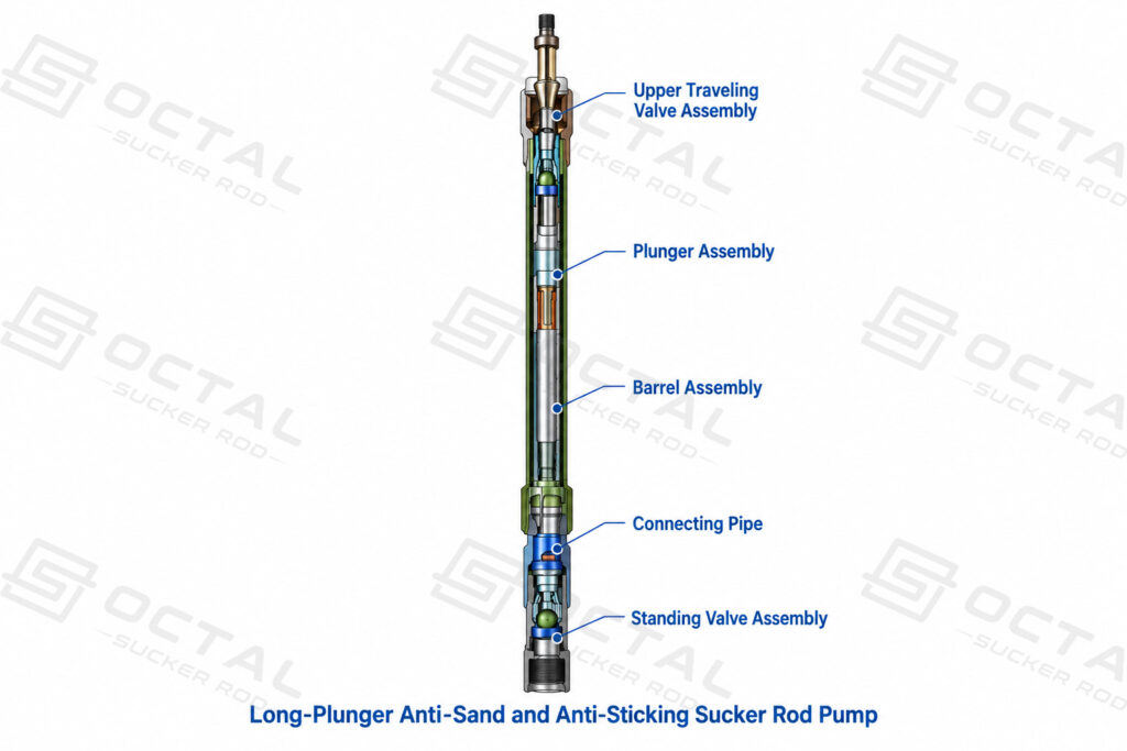
The long-plunger anti-sand-sticking sucker rod pump combines an extended plunger with a short barrel to reduce sand accumulation around the plunger and sealing surfaces, helping limit sticking and abrasive wear in fine-sand wells. Its upper outlet valve cover extends beyond the barrel, increasing the available flow area and strengthening the overall assembly, while the enlarged outlet passage helps reduce sand-related blockage. The lower connecting pipe has a larger internal diameter than the pump barrel, reducing fluid-flow resistance during the downward stroke.
This pump is suitable for fine-sand-producing wells and may also be used in wells containing corrosive fluids such as H₂S, CO₂ and salt water. Where sand production and corrosion occur together, the valve materials and surface treatments should be selected according to the actual fluid composition and downhole conditions.
Specifications
| Parameter | Catalog specification |
|---|---|
| Nominal pump diameter | 28, 31.75, 38.1, 44.45, 57.15 and 69.85 mm |
| Barrel length | 1.2 m |
| Plunger length | 3.0–9.0 m |
| Stroke length | 1.8–8.0 m |
| Clearance code | I and II |
| Parameter | 28 mm | 31.75 mm | 38.1 mm | 44.45 mm | 57.15 mm | 69.85 mm |
|---|---|---|---|---|---|---|
| Pump body connection thread, up/down | 2 7/8 in NU | 2 7/8 in NU | 2 7/8 in NU | 2 7/8 in NU | 3 1/2 in NU | 3 1/2 in NU |
| Sucker rod thread | 3/4 in | 3/4 in | 3/4 in | 3/4 in | 3/4 in | 7/8 in |
| Maximum OD (mm) | 88.9 | 88.9 | 88.9 | 88.9 | 108 | 108 |
| Pump constant (m³/d) | 0.88 | 1.14 | 1.64 | 2.24 | 3.69 | 5.5 |
Long-Plunger Sand-Settling Sucker Rod Pump
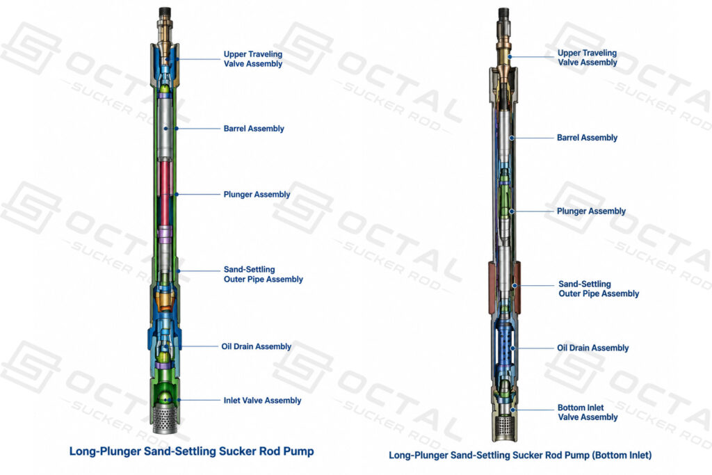
The long-plunger sand-settling sucker rod pump combines a long plunger, a short barrel and a dedicated sand-settling structure to reduce sand accumulation around the working barrel and plunger. Its extended outlet valve cover increases the available flow area and strengthens the assembly, helping reduce sand-related blockage and fluid-flow resistance. The pump is available in two inlet configurations: lateral-inlet and bottom-inlet, which use different flow paths to manage sand entering the pump.
In the lateral-inlet configuration, the oil-inlet passage is separated from the sand-settling channel. During pumping, sand in the produced fluid can enter the settling passage and move into the sand-settling liner rather than accumulating inside the working barrel. In the bottom-inlet configuration, the lower inlet and settling structure direct sand toward the lower sand-settling section, helping limit sand accumulation in the barrel during pumping and reduce the risk of sand-related sticking when pumping stops.
Both configurations are suitable for selected fine-sand-producing wells, wells containing coal powder and coalbed methane wells. The bottom-inlet design can also be used in certain deeper wells requiring downhole tools or extended-liner arrangements. Choose the lateral-inlet or bottom-inlet configuration according to the well completion, expected solids loading, available installation space and required inlet-flow path.
Specifications — Lateral-Inlet Configuration
| Parameter | Catalog specification |
|---|---|
| Nominal pump diameter | 28, 31.75, 38.1, 44.45, 57.15 and 69.85 mm |
| Barrel length | 1.2 m |
| Plunger length | 3.0–9.0 m |
| Stroke length | 1.8–8.0 m |
| Clearance code | I and II |
| Parameter | 28 mm | 31.75 mm | 38.1 mm | 44.45 mm | 57.15 mm | 69.85 mm |
|---|---|---|---|---|---|---|
| Pump body connection thread, up/down | 2 7/8 in NU | 2 7/8 in NU | 2 7/8 in NU | 2 7/8 in NU | 3 1/2 in NU | 3 1/2 in NU |
| Sucker rod thread | 3/4 in | 3/4 in | 3/4 in | 3/4 in | 3/4 in | 7/8 in |
| Maximum OD (mm) | 108 | 108 | 108 | 108 | 108 | 121 |
| Pump constant (m³/d) | 0.88 | 1.14 | 1.64 | 2.24 | 3.69 | 5.5 |
Specifications — Bottom-Inlet Configuration
| Parameter | Catalog specification |
|---|---|
| Nominal pump diameter | 28, 31.75, 38.1, 44.45, 57.15 and 69.85 mm |
| Barrel length | 1.2 m |
| Plunger length | 3.0–9.0 m |
| Stroke length | 1.8–8.0 m |
| Clearance code | I and II |
| Parameter | 28 mm | 31.75 mm | 38.1 mm | 44.45 mm | 57.15 mm | 69.85 mm |
|---|---|---|---|---|---|---|
| Pump body connection thread, up/down | 2 7/8 in NU | 2 7/8 in NU | 2 7/8 in NU | 2 7/8 in NU | 3 1/2 in NU | 3 1/2 in NU |
| Sucker rod thread | 3/4 in | 3/4 in | 3/4 in | 3/4 in | 3/4 in | 7/8 in |
| Maximum OD (mm) | 108 | 108 | 108 | 108 | 108 | 121 |
| Pump constant (m³/d) | 0.88 | 1.14 | 1.64 | 2.24 | 3.69 | 5.5 |
Anti-Gas Sucker Rod Pump Series
Gas entering the pump barrel can reduce liquid displacement by occupying part of the working chamber and interfering with valve operation, particularly in wells with high gas production and low dynamic fluid levels. Anti-gas sucker rod pumps address these conditions through two different designs: the hollow anti-gas sucker rod pump uses a hollow coupling to help reduce gas interference within the pump, while the sucker rod pump with a forced mechanical valve uses an independently operating, multi-stage sealing structure to support valve operation under gas-producing conditions. The hollow design is suited to high gas-to-oil ratio wells and applications requiring greater pump setting depths, while the forced-mechanical-valve design can be used in conventional, light-oil, sandy, highly deviated, horizontal and high-gas wells. Selection depends on gas production, dynamic fluid level, pump setting depth, well geometry and the required pump configuration.
Hollow Anti-Gas Sucker Rod Pump
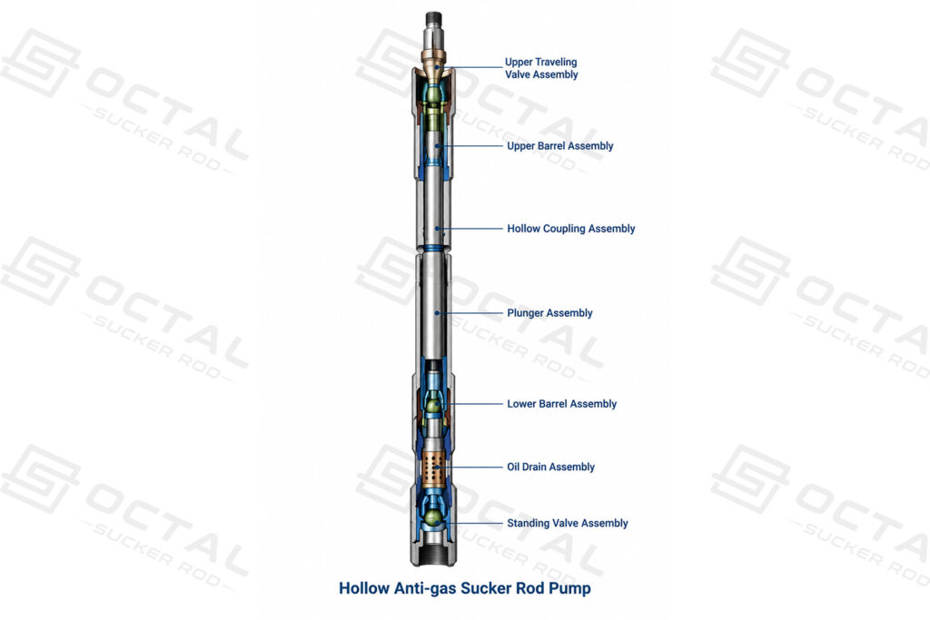
The hollow anti-gas sucker rod pump uses a hollow coupling assembly and an internal flow arrangement designed to reduce gas interference and improve pumping efficiency. Its guided valve cover features a large internal flow passage to support valve movement, while the reinforced barrel improves mechanical strength. A sealing ring at the plunger connection helps limit corrosive fluid exposure at the threads, and valve material selection should account for the expected wear, corrosion and well conditions.
This pump is primarily intended for oil wells with a high gas-to-oil ratio and a high pump setting depth. Its hollow coupling structure helps manage gas interference within the pump, but performance also depends on the amount of gas entering the intake and the well’s operating conditions. Selection should therefore account for the expected gas fraction at the pump intake, dynamic fluid level, fluid properties, pressure conditions and pump submergence.
Specifications
| Parameter | 28 mm | 31.75 mm | 38.1 mm | 44.45 mm | 57.15 mm | 69.85 mm | 82.55 mm | 95.25 mm |
|---|---|---|---|---|---|---|---|---|
| Plunger length (mm) | 1,200 | 1,200 | 1,200 | 1,200 | 1,200 | 1,200 | 1,200 | 1,200 |
| Barrel length (mm) | 3,000–12,000 | 3,000–12,000 | 3,000–12,000 | 3,000–12,000 | 3,000–12,000 | 3,000–12,000 | 3,000–12,000 | 3,000–12,000 |
| Upper tubing connection | 2 7/8 in NU | 2 7/8 in NU | 2 7/8 in NU | 2 7/8 in NU | 2 7/8 in NU | 3 1/2 in NU | 4 in NU | 4 1/2 in NU |
| Lower tubing connection | 2 7/8 in NU | 2 7/8 in NU | 2 7/8 in NU | 2 7/8 in NU | 2 7/8 in NU | 2 7/8 in NU | 3 1/2 in NU | 3 1/2 in NU |
| Sucker rod thread | 3/4 in | 3/4 in | 3/4 in | 3/4 in | 3/4 in | 7/8 in | 1 in | 1 in |
| Pump constant (m³/d) | 0.88 | 1.14 | 1.64 | 2.24 | 3.69 | 5.5 | 7.79 | 10.2 |
| Maximum OD (mm) | 88.9 | 88.9 | 88.9 | 88.9 | 88.9 | 108 | 114 | 132 |
Sucker Rod Pump with Forced Mechanical Valve
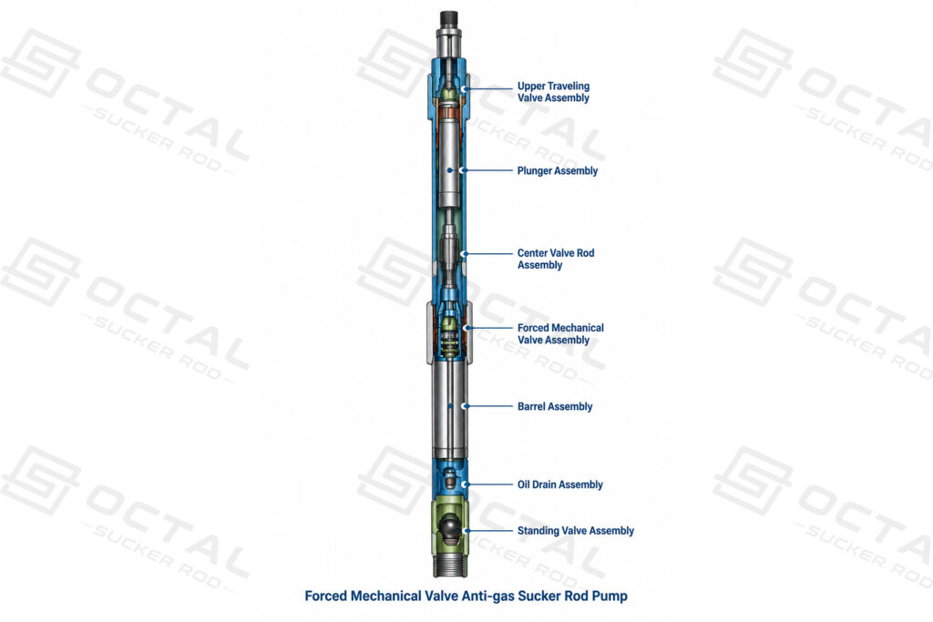
The sucker rod pump with forced mechanical valve uses a specialized mechanical valve and a multi-section sealing structure to address gas interference under different downhole operating conditions. The sealing sections operate independently, while the guided valve assembly provides a large flow passage to support valve movement. A special stainless-steel valve cover improves corrosion resistance, and the center-rod arrangement helps reduce eccentric wear in suitable deviated and horizontal wells. Compared with the hollow anti-gas sucker rod pump, this design relies on a different valve-actuation and sealing arrangement to manage gas-related pumping problems.
This pump can be used in conventional oil wells, light-oil wells, sand-producing wells, highly deviated wells, horizontal wells and high-gas wells. Select the pump based on gas production, dynamic fluid level, solids loading, well deviation and completion requirements.Confirm that the tubing connection and sucker rod thread match the corresponding connections, and that the pump’s maximum outside diameter fits the available installation space.
Specifications
| Parameter | 38.1 mm | 44.45 mm | 57.15 mm | 69.85 mm | 82.55 mm | 95.25 mm |
|---|---|---|---|---|---|---|
| Stroke length (m) | 2.7–7.2 | 2.7–7.2 | 2.7–7.2 | 2.7–7.2 | 2.7–7.2 | 2.7–7.2 |
| Barrel length (m) | 4.5–9.0 | 4.5–9.0 | 4.5–9.0 | 4.5–9.0 | 4.5–9.0 | 4.5–9.0 |
| Plunger length (m) | 0.6/0.6 | 0.6/0.6 | 0.6/0.6 | 0.6/0.6 | 0.6/0.6 | 0.6/0.6 |
| Pump body connection thread, up/down | 2 7/8 in NU | 2 7/8 in NU | 2 7/8 in NU | 3 1/2 in NU | 4 in NU | 4 1/2 in NU |
| Sucker rod thread | 3/4 in | 3/4 in | 3/4 in | 7/8 in | 1 in | 1 in |
| Maximum OD (mm) | 88.9 | 88.9 | 88.9 | 108 | 114 | 132 |
| Pump constant (m³/d) | 1.64 | 2.24 | 3.69 | 5.54 | 7.79 | 10.2 |
How Does a Sucker Rod Pump Work?
A sucker rod pump uses a reciprocating positive-displacement mechanism to lift well fluid through the production tubing. The surface pumping unit drives the sucker rod string and downhole plunger, while two one-way valves control fluid movement: the standing valve at the bottom of the pump barrel and the traveling valve inside the plunger. Their alternating operation draws well fluid into the pump barrel and transfers it upward through the production tubing.
Sucker Rod Pump Operating Cycle
| Pumping stage | Standing valve | Traveling valve | Fluid movement |
|---|---|---|---|
| Upstroke | Opens as chamber pressure falls | Closes under the fluid-column pressure | Well fluid enters the pump barrel while fluid above the plunger is lifted through the tubing. |
| Downstroke | Closes as chamber pressure rises | Opens when the pressure difference permits flow | Fluid passes through the plunger into the chamber above it, ready to be lifted during the next upstroke. |
How Pump Design Affects Downhole Performance
Although the basic pumping cycle is similar, the barrel, plunger, valve assembly, inlet passages and sealing structure vary according to the well’s operating conditions. Wear-resistant and corrosion-resistant pumps use suitable materials and surface treatments to address abrasive solids and corrosive fluids. Long-plunger anti-sand-sticking and sand-settling pumps use different structural arrangements to limit sand accumulation, while anti-gas pumps modify internal flow paths or valve mechanisms to address gas interference.
Installation and retrieval also depend on pump design. A tubing pump is installed as part of the production tubing assembly, whereas an insert-type sucker rod pump can be retrieved through the tubing using the sucker rod string when the well completion supports this method. These differences affect maintenance procedures, intervention requirements and pump selection.
How to Select the Right Sucker Rod Pump for Well Conditions
Selecting the right sucker rod pump requires matching the pump design to the well’s production requirements, downhole fluid conditions and completion dimensions. Corrosion, sand accumulation, plunger sticking and gas interference each place different demands on the pump’s materials and internal structure. Nominal diameter and pump constant help establish the required displacement, while barrel length, plunger design, valve configuration and connection dimensions determine whether the selected pump is suitable for the intended operating conditions.
| Well condition | Pump types to evaluate | Main selection considerations |
|---|---|---|
| Corrosive fluids containing H₂S, CO₂ or salt water | Anti-wear and anti-corrosion tubing pump; anti-wear and anti-corrosion rod pump | Fluid chemistry, temperature, material compatibility and specified coatings |
| Fine sand causing plunger sticking | Long-plunger anti-sand-sticking pump | Plunger length, barrel length, clearance code and solids loading |
| Sand accumulation requiring a dedicated settling passage | Long-plunger sand-settling pump | Lateral or bottom inlet, settling passage, completion geometry and solids production |
| High gas–oil ratio or gas interference | Hollow anti-gas pump; pump with forced mechanical valve | Gas fraction, dynamic fluid level, pump submergence and valve arrangement |
| Low-liquid-level, low-production deep wells | Anti-wear and anti-corrosion rod pump, where its stated limits are met | Pump setting depth, liquid supply, seating configuration and retrieval requirements |
| Deviated or horizontal wells | Product-specific rod pump or anti-gas configuration | Deviation, eccentric wear risk, completion geometry and model-specific operating limits |
Reliable sucker rod pump selection requires a combined assessment of well conditions, pump construction, completion geometry and operating requirements. Nominal diameter and pump constant alone cannot establish suitability; dimensional compatibility, material selection, valve configuration, installation method and model-specific operating limits must also be verified. Accurate well data and confirmed technical specifications provide the basis for a suitable configuration and help reduce avoidable problems during installation and operation.
Octal supports oilfield customers with sucker rod pump solutions for different well conditions and operating requirements. By reviewing application requirements, dimensional specifications and connection details, Octal helps customers identify suitable pump configurations and clarify technical requirements before ordering. Technical documentation and model-specific specification confirmation support the purchasing process, helping ensure that the selected equipment aligns with the project’s completion design and operating conditions.
FAQ
Q:Which Sucker Rod Pump Is Suitable for Sand-Producing Wells?
A:A long-plunger anti-sand-sticking sucker rod pump is designed to reduce sand-related sticking around the plunger and barrel. A long-plunger sand-settling sucker rod pump adds a dedicated passage to direct sand away from the working barrel. The choice depends on sand production characteristics, the required inlet configuration and the well completion.
Q:Can Sucker Rod Pumps Be Used in Wells Containing H₂S, CO₂ or Salt Water?
A:Yes, suitable anti-wear and corrosion-resistant sucker rod pump configurations are available for corrosive well conditions. Material and coating selection must account for fluid composition, temperature, pressure and wear conditions. For sour-service applications, the selected materials and pump configuration must also meet the project’s applicable requirements.
Q:What Information Is Needed to Select a Sucker Rod Pump?
A:Pump selection requires the nominal pump diameter, barrel and plunger lengths, stroke length, maximum outside diameter, tubing connection threads, sucker rod thread and required pump displacement. Well depth, completion arrangement, fluid composition, sand production and gas interference should also be provided to identify a suitable pump configuration.
Q:What Is the Difference Between a Tubing Pump and an Insert-Type Sucker Rod Pump?
A:A tubing pump is installed as part of the production tubing assembly, while an insert-type sucker rod pump is installed inside the tubing and can be retrieved through the sucker rod string in a compatible completion. The appropriate design depends on the required pump capacity, tubing configuration, anchoring arrangement and maintenance requirements.