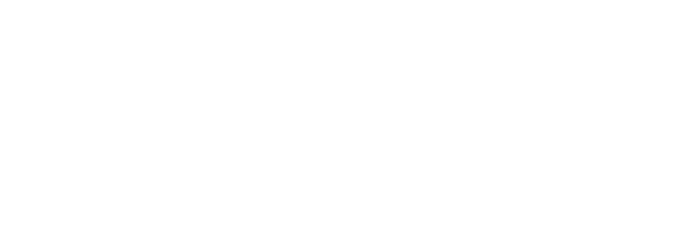
Grade K sucker rod is a nickel-molybdenum alloy-steel sucker rod classified under API Spec 11B for use in reciprocating rod-lift systems. It consists of a solid, heat-treated steel body with forged upset ends, wrench flats and threaded pins. Individual rods connect through couplings to form a rod string between the surface pumping unit and the downhole pump, transmitting reciprocating motion and tensile load to operate the pump.
Grade K is characterized by moderate mechanical strength and alloy chemistry developed for improved corrosion resistance. It belongs to the same nominal tensile-strength range as Grade C, with its principal distinction being the material composition used for corrosive production conditions. Typical applications include oil wells with moderate rod loads where corrosion is an important selection factor. Suitability depends on the calculated rod-string stresses, produced-fluid chemistry and corrosion-control measures.
Product Data
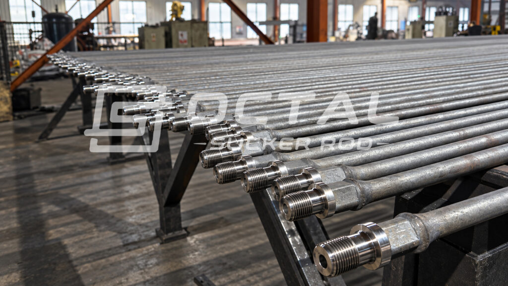
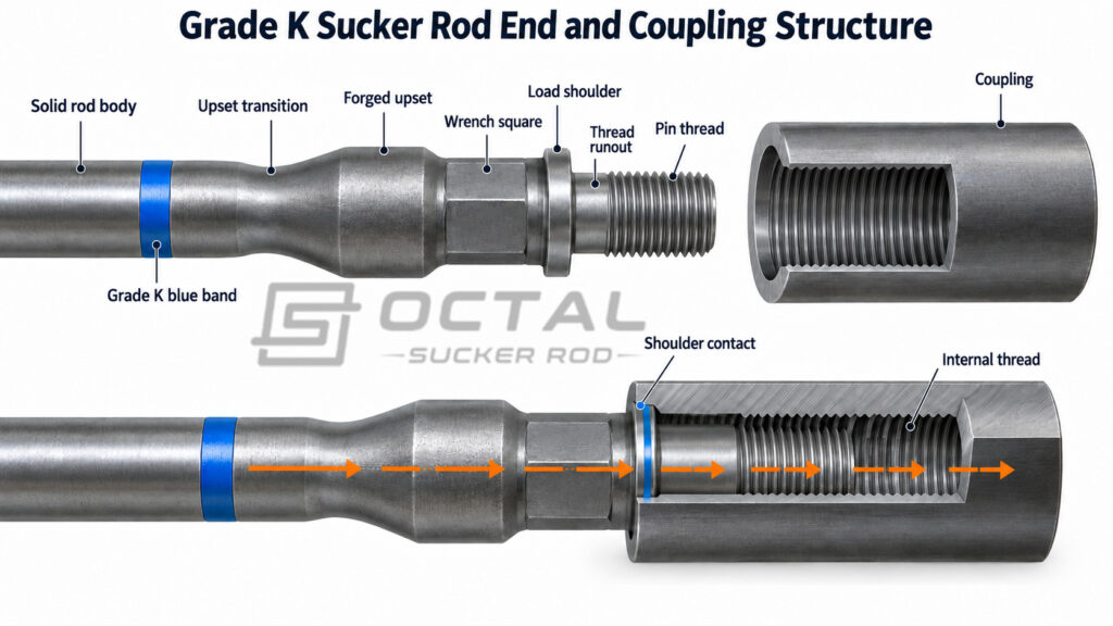
Grade K is supplied as an alloy steel sucker rod with forged ends, wrench squares, load shoulders and API pin threads. Dimensions, threads, mechanical properties, marking and inspection should comply with the edition of API Spec 11B stated in the purchase order.
| Item | Grade K sucker rod specification |
|---|---|
| Applicable standard | API Spec 11B and applicable purchase-order requirements |
| Material classification | Alloy steel |
| Typical UNS material family | G43XX0 or G46XX0 series |
| Typical metallurgy | Nickel-molybdenum alloy steel |
| Minimum yield strength | 60,000 psi / 414 MPa |
| Tensile-strength range | 90,000–115,000 psi / 621–793 MPa |
| Minimum elongation | 13% over a 200 mm gauge length |
| Minimum reduction of area | 50% under the referenced factory specification |
| Factory fatigue-life reference | At least 1.0 × 10⁶ cycles |
| Standard identification color | Blue |
| Common nominal diameters | 5/8–1 1/8 in. / 15.88–28.58 mm |
| Common nominal lengths | 25 ft and 30 ft / 7.62 m and 9.14 m |
| End configuration | Forged upset, wrench square, shoulder and API pin |
| Connection component | Full-size or slim-hole sucker rod coupling, as specified |
| Standard surface condition | Bare steel with temporary storage protection |
| Optional surface protection | Project-specific corrosion-resistant coating |
| Traceability | Steel heat, production lot, grade, diameter and length |
The reduction-of-area and fatigue values shown above are supply specifications taken from the referenced manufacturing data. They should be included in the approved technical data sheet when they are required as contractual acceptance criteria.
Grade K vs Grade C and Grade D
The following comparison explains the actual position of Grade K within the common API sucker rod range.
| Property | Grade C | Grade K | Grade D |
|---|---|---|---|
| Material type | Carbon-manganese steel | Nickel-molybdenum alloy steel | Carbon, alloy or special-alloy steel, depending on subtype |
| Minimum yield strength | 60,000 psi / 414 MPa | 60,000 psi / 414 MPa | 85,000 psi / 586 MPa |
| Minimum tensile strength | 90,000 psi / 621 MPa | 90,000 psi / 621 MPa | 115,000 psi / 793 MPa |
| Maximum tensile strength | 115,000 psi / 793 MPa | 115,000 psi / 793 MPa | 140,000 psi / 965 MPa |
| Minimum elongation | 13% | 13% | 13% |
| Factory reduction-of-area target | At least 50% | At least 50% | At least 50% |
| Factory fatigue-life value provided | Not stated | At least 1.0 × 10⁶ cycles | Not stated |
| API color identification | White | Blue | Yellow for Grade DA |
| Relative load capacity | Moderate | Moderate | Higher |
| Corrosion-service positioning | Noncorrosive or effectively inhibited wells | Corrosive wells under moderate loading | Higher-load wells with effective corrosion control |
| Typical well category | Shallow, low-load service | Shallow to medium-depth corrosive service | Medium to deep, higher-load service |
Grade K should therefore be described as a moderate-strength, corrosion-oriented grade rather than a mechanically intermediate grade. Grade D carries greater tensile load, but higher strength alone does not guarantee longer service life in an uninhibited corrosive well.
Typical Chemical Composition
The composition below represents published manufacturer chemistry for commonly supplied API rod grades. It provides a useful material comparison but does not replace the heat analysis on the mill test certificate.
| Element | Grade C carbon steel | Grade K alloy steel | Grade D alloy example |
|---|---|---|---|
| Carbon, C | 0.30–0.36% | 0.18–0.25% | 0.40–0.45% |
| Manganese, Mn | 1.30–1.60% | 0.70–0.90% | 0.75–1.00% |
| Silicon, Si | 0.20–0.40% | 0.15–0.35% | 0.15–0.35% |
| Sulfur, S | 0.035% maximum | 0.035% maximum | 0.025% maximum |
| Phosphorus, P | 0.035% maximum | 0.035% maximum | 0.025% maximum |
| Chromium, Cr | 0.20% maximum | 0.30% maximum | 0.80–1.10% |
| Nickel, Ni | 0.15% maximum | 1.65–2.00% | 0.25% maximum |
| Molybdenum, Mo | 0.05% maximum | 0.20–0.30% | 0.15–0.25% |
| Vanadium, V | 0.15% maximum | Not normally specified | Not normally specified |
Grade K contains substantially more nickel than the Grade C and conventional Grade D examples in this table. Nickel supports toughness and helps maintain more stable mechanical behavior in corrosive cyclic service. Molybdenum contributes to hardenability and allows the required rod-body properties to be obtained through controlled heat treatment.
The Grade D row represents a common chromium-molybdenum Grade DA composition. Grade D can also be produced from other API-permitted carbon, alloy or special-alloy material families, so its chemical composition must be confirmed by subtype and mill certificate.
Corrosion and Fatigue Performance
Grade K sucker rod performance depends on the tensile stress cycle and the condition of the exposed steel surface. Corrosion pits and mechanical damage can initiate fatigue cracks at nominal stresses below the material’s yield strength. Evaluation therefore requires both a rod-string stress assessment and corrosion test results obtained under defined conditions.
Cyclic Stress Reference
A modified Goodman calculation provides a preliminary check of the allowable tensile stress during reciprocating pumping. The following example uses published Grade K coefficients and minimum tensile strength.
| Calculation Parameter | Value or Relationship | Basis |
|---|---|---|
| Minimum ultimate tensile strength, UTS | 621 MPa | Published Grade K reference |
| Maximum allowable tensile stress, Sₐ | (UTS ÷ 4 + 0.5625 × Smin) × SF | Published modified Goodman relationship |
| Minimum tensile stress, Smin | Calculated or measured at the rod section being evaluated | Rod-string loading |
| Service factor, SF | 0.90 for this example | Manufacturer reference for corrosive environments; subject to application review |
| Preliminary acceptance condition | Smax ≤ Sₐ | Maximum operating stress must remain within the calculated limit |
The service factor requires review against actual corrosion severity, rod condition and operating experience. It is not a universal qualification for corrosive service.
| Assumed Minimum Stress | Calculated Maximum Allowable Stress | Allowable Stress Range |
|---|---|---|
| 50 MPa | 165.0 MPa | 115.0 MPa |
| 100 MPa | 190.4 MPa | 90.4 MPa |
| 150 MPa | 215.7 MPa | 65.7 MPa |
Calculated examples, not measured fatigue limits or guaranteed product performance.
As minimum tensile stress increases, the allowable stress range decreases. Increasing the steady tensile load therefore leaves less room for cyclic loading. This check does not account directly for local bending, damaged threads or stress concentration at corrosion pits.
Fatigue-Test Reporting
A fatigue-life claim becomes useful only when the applied stress cycle and test environment are reported alongside the number of cycles.
| Test Parameter | Required Numerical Information | Interpretation |
|---|---|---|
| Declared endurance reference | ≥1.0 × 10⁶ cycles, only if supported by a test report | Identify whether this represents a runout without failure or a specified acceptance target |
| Applied stress | Smax and Smin, MPa | Defines the loading severity |
| Stress amplitude | (Smax − Smin) ÷ 2, MPa | Quantifies the alternating component |
| Stress ratio | R = Smin ÷ Smax | Allows comparison of tests with different mean stresses |
| Test frequency | Hz | Required when assessing time-dependent corrosion effects |
| Test population | Number tested, number failed and individual cycle counts | Shows repeatability and scatter |
| Test environment | Temperature, °C; pH; fluid composition and gas partial pressures | Distinguishes air-fatigue results from corrosion-fatigue results |
The test report should identify the specimen geometry, heat treatment and surface condition. Rod-body testing does not establish the fatigue endurance of a complete threaded connection. A specimen that reaches the stopping point without failure demonstrates survival under that particular test condition.
Corrosion Evaluation
Corrosion resistance should be expressed through measured metal loss, localized attack and cracking results. Laboratory immersion testing following ASTM G31 requires defined solution chemistry, temperature, exposure time and fluid conditions so that results can be interpreted and compared.
| Evaluation Item | Quantitative Result to Report | Engineering Interpretation |
|---|---|---|
| General corrosion | Mass loss, mg; exposed area, cm²; duration, h; calculated rate, mm/year | Measures average metal loss over the test exposure |
| Localized corrosion | Maximum pit depth, µm or mm, with exposure duration | Identifies concentrated attack that average mass loss can conceal |
| Test-fluid chemistry | Chloride concentration, mg/L; pH; dissolved oxygen, mg/L | Establishes the environment represented by the result |
| Gas exposure | CO₂ and H₂S partial pressures, kPa or bar; temperature, °C | Defines the gas-exposure conditions |
| Inhibitor response | Untreated and treated corrosion rates, mm/year; inhibitor dosage, mg/L | Quantifies protection under otherwise matched conditions |
| Sulfide stress cracking | Applied stress, MPa or % of yield strength; exposure time, h; cracking result | Requires separate qualification under a defined sour-service test procedure |
General corrosion rate, pit depth and cracking susceptibility should be evaluated separately. A low average corrosion rate does not establish resistance to localized attack or sulfide stress cracking. NACE TM0177 provides methods for evaluating cracking resistance in hydrogen-sulfide environments; a Grade K designation alone does not demonstrate a passing result.
Comparisons between Grade K and other grades require consistent test conditions, including:
- Specimen geometry, surface preparation and heat-treatment condition;
- Applied maximum and minimum stress;
- Fluid chemistry, gas partial pressures and temperature;
- Exposure duration, test frequency and inhibitor treatment.
Product-specific corrosion rates and fatigue results should be supported by laboratory reports identifying these conditions. Laboratory endurance should not be converted directly into guaranteed field service life.
Corrosion-Service Comparison
| Selection factor | Grade C | Grade K | Grade D |
|---|---|---|---|
| Uninhibited corrosive service | Generally not preferred | Better candidate within its load range | Requires careful review |
| Effectively inhibited production fluid | Suitable for lower loads | Suitable | Suitable for higher loads |
| Moderate cyclic load with corrosion present | Limited preference | Preferred API grade among the three | Possible if corrosion is controlled |
| High calculated rod-string load | Often inadequate | Often inadequate | Better mechanical choice |
| Severe pitting history | Upgrade corrosion control before grade selection | Review fluid chemistry and pit mechanism | Higher strength may increase notch sensitivity |
| High well deviation | Requires friction analysis | Requires friction analysis | Requires friction analysis |
| Sour-service exposure | Not automatically qualified | Not automatically qualified | Not automatically qualified |
| Primary selection advantage | Low-cost standard service | Corrosion-oriented alloy chemistry | Higher mechanical load capacity |
This comparison does not mean Grade K is immune to corrosion. It means its chemistry is more appropriate than Grade C for many corrosive wells where the required load remains within the Grade K mechanical envelope.
Standard Sizes and Body-Diameter Tolerances
| Nominal size | Nominal diameter | Positive tolerance | Negative tolerance |
|---|---|---|---|
| 5/8 in. | 15.88 mm | +0.18 mm | −0.36 mm |
| 3/4 in. | 19.05 mm | +0.20 mm | −0.41 mm |
| 7/8 in. | 22.23 mm | +0.20 mm | −0.41 mm |
| 1 in. | 25.40 mm | +0.23 mm | −0.46 mm |
| 1 1/8 in. | 28.58 mm | +0.25 mm | −0.51 mm |
Body diameter affects tensile area, rod-string weight, fluid-flow area and the clearance available between the rod and tubing. The largest diameter is not automatically the best choice because it increases suspended weight and can restrict annular flow.
Forged-End Dimensions
The table below provides commonly controlled end dimensions from the referenced manufacturing data.
| Nominal rod size | External shoulder diameter | Wrench-square width | Wrench-square length |
|---|---|---|---|
| 5/8 in. | 31.75 mm, +0.13/−0.25 mm | 22.23 mm, ±0.79 mm | 31.75 mm |
| 3/4 in. | 38.10 mm, +0.13/−0.25 mm | 25.40 mm, ±0.79 mm | 31.75 mm |
| 7/8 in. | 41.30 mm, +0.13/−0.25 mm | 25.40 mm, ±0.79 mm | 31.75 mm |
| 1 in. | 50.80 mm, +0.13/−0.25 mm | 33.34 mm, ±0.79 mm | 38.10 mm |
| 1 1/8 in. | 57.15 mm, ±0.38 mm | 38.10 mm, ±0.79 mm | 41.28 mm |
Correct forged-end geometry allows the rod to be handled through the wrench square while maintaining sufficient material around the pin and shoulder. Upset transitions should be smooth because abrupt changes in section increase local fatigue stress.
Standard Lengths
| Nominal rod length | Metric equivalent | Reference length tolerance |
|---|---|---|
| 25 ft | 7.62 m | ±2.0 in. / ±50 mm |
| 30 ft | 9.14 m | ±2.0 in. / ±50 mm |
Actual measurement points and effective assembled length should follow the approved API drawing. Pony rods can be used to adjust the completed string length where a standard sucker rod does not match the required pump setting.
Pulling-Force Reference
The values below are manufacturer reference limits for a like-new rod string. They are calculated from the smallest effective section using a defined proportion of minimum yield strength.
| Nominal rod diameter | Reference maximum pull | Metric equivalent | Calculation basis |
|---|---|---|---|
| 5/8 in. | 15.8 klbf | 70.3 kN | 90% of minimum yield strength |
| 3/4 in. | 22.8 klbf | 101.4 kN | 90% of minimum yield strength |
| 7/8 in. | 31.3 klbf | 139.2 kN | 90% of minimum yield strength |
| 1 in. | 40.9 klbf | 181.9 kN | 90% of minimum yield strength |
| 1 1/8 in. | 51.8 klbf | 230.4 kN | 90% of minimum yield strength |
These values are pulling references rather than allowable cyclic operating loads. Rod-string design should consider minimum and maximum stress, fatigue loading, corrosion service factor, well deviation, pump load and the remaining section of used rods.
Rod-String Design Limits
Grade K sucker rod selection requires a load assessment for each section of the rod string. Rod diameter determines the nominal axial stress, while the maximum and minimum loads during pumping determine fatigue demand. Corrosion, wear, well deviation and connection condition can further restrict the usable load range.
Rod Diameter and Axial Stress
Nominal axial stress is calculated by dividing the tensile load at the section under review by its cross-sectional area.
| Calculation Item | Relationship | Units and Conditions |
|---|---|---|
| Solid rod-body area, A | πd² ÷ 4 | d in mm; A in mm² |
| Nominal axial stress, σ | F ÷ A | F in N; σ in MPa |
| Maximum cycle stress, Smax | Fmax ÷ A | Use the maximum local tensile load |
| Minimum cycle stress, Smin | Fmin ÷ A | Use the minimum local tensile load |
| Cyclic stress range, ΔS | Smax − Smin | MPa |
| Mean stress, Sm | (Smax + Smin) ÷ 2 | MPa |
| Stress amplitude, Sa | (Smax − Smin) ÷ 2 | MPa |
The following comparison applies the same tensile load to different nominal rod-body diameters.
| Nominal Rod Diameter | Calculated Body Area | Applied Tensile Load | Nominal Axial Stress |
|---|---|---|---|
| 5/8 in | 197.9 mm² | 50 kN | 252.6 MPa |
| 3/4 in | 285.0 mm² | 50 kN | 175.4 MPa |
| 7/8 in | 387.9 mm² | 50 kN | 128.9 MPa |
| 1 in | 506.7 mm² | 50 kN | 98.7 MPa |
| 1 1/8 in | 641.3 mm² | 50 kN | 78.0 MPa |
Calculated from nominal inch diameters before rounding. Values describe an unworn, solid rod body under axial tension; they are not allowable operating loads.
A larger rod diameter reduces stress under the same local load. However, increasing diameter also increases rod-string weight. Taper selection must therefore account for the weight and dynamic response of the complete string. Surface polished-rod load should not be applied unchanged to every downhole section.
Worked Fatigue Check
The example below shows why remaining below yield strength does not, by itself, establish acceptable cyclic loading. It uses the modified Goodman relationship described in the corrosion and fatigue section.
| Parameter | Example Value | Basis |
|---|---|---|
| Rod diameter | 7/8 in | Assumed nominal rod size |
| Rod-body area | 387.9 mm² | Calculated |
| Minimum local tensile load | 20 kN | Assumed cycle minimum |
| Maximum local tensile load | 70 kN | Assumed cycle maximum |
| Minimum tensile stress, Smin | 51.6 MPa | Calculated |
| Maximum tensile stress, Smax | 180.4 MPa | Calculated |
| Cyclic stress range | 128.9 MPa | Calculated |
| Grade K minimum yield-strength reference | 414 MPa | Static material reference |
| Grade K minimum tensile-strength reference | 621 MPa | Input to the fatigue calculation |
| Service factor, SF | 0.90 | Illustrative selection; requires application review |
| Allowable maximum stress, Sallow | (621 ÷ 4 + 0.5625 × 51.6) × 0.90 ≈ 165.8 MPa | Modified Goodman calculation |
| Stress utilization | 108.8% | Smax ÷ Sallow × 100 |
| Preliminary fatigue-screening criterion | ≤100% utilization | Applies only within this calculation method |
| Example assessment | Exceeds calculated limit | Revise diameter, loading or grade selection |
Illustrative calculation, not a field test or product performance guarantee. Calculations use unrounded intermediate values.
The example remains below the material’s minimum yield strength but exceeds the calculated cyclic stress limit. Corrective action can include revising the rod taper, reducing dynamic loading or selecting a suitable higher-strength rod. Any change requires recalculation of the complete string.
Effect of Rod-Body Wear
Loss of cross-sectional area increases nominal stress even when the applied tensile load remains unchanged. The following calculation assumes uniform diameter reduction over a circular rod section.
| Uniform Diameter Reduction | Remaining Cross-sectional Area | Increase in Nominal Axial Stress at the Same Load |
|---|---|---|
| 0% | 100.00% | 0.0% |
| 2% | 96.04% | 4.1% |
| 5% | 90.25% | 10.8% |
| 10% | 81.00% | 23.5% |
Geometric calculations only. These percentages are not permissible wear limits or reuse acceptance criteria.
Localized pitting and one-sided tubing wear require separate evaluation. They produce irregular sections and local stress concentrations that cannot be represented adequately by uniform diameter reduction.
Additional Design Checks
| Design Item | Quantitative Input or Check | Application Limit |
|---|---|---|
| Rod taper | Diameter in mm, section length in m and maximum/minimum load in kN for each section | Check every taper section and connection |
| Well deviation | Inclination in degrees; dogleg severity in °/30 m or °/100 ft; contact load in N/m | Guide spacing requires trajectory and contact analysis |
| Downstroke compression | Minimum effective axial force in kN | Compression requires buckling and tubing-contact assessment |
| Retrieval loading | Local tensile load in kN, remaining section in mm² and condition-adjusted strength | Retrieval limits must not be used as cyclic operating ratings |
| PCP combined loading | Axial stress σ = 4F/(πd²); torsional shear τ = 16T/(πd³); equivalent stress σeq = √(σ² + 3τ²) | Use F in N, T in N·mm and d in mm; connection torque capacity requires a separate check |
Grade K selection requires acceptable cyclic stress, adequate connection capacity and allowance for corrosion, wear and well deviation.
Manufacturing and Inspection Controls
| Production stage | Controlled characteristic | Acceptance evidence |
|---|---|---|
| Raw-material receipt | Heat chemistry and steel cleanliness | Mill test certificate and heat identification |
| Bar inspection | Internal and surface discontinuities | Electromagnetic or ultrasonic inspection record |
| Cutting and straightening | Length, straightness and surface condition | Dimensional inspection |
| End heating | Controlled heating zone and temperature uniformity | Furnace and process records |
| Upset forging | Metal flow, transition profile and end dimensions | Visual and dimensional inspection |
| Heat treatment | Yield strength, tensile strength and ductility | Heat-treatment chart and mechanical test report |
| Hot-tension straightening | Rod straightness without severe local deformation | Straightness measurement |
| Shoulder machining | Diameter, flatness and surface condition | Calibrated dimensional inspection |
| Thread production | Profile, pitch diameter, taper and effective length | Calibrated API working gauges |
| Surface inspection | Cracks, laps, seams, pits and handling marks | Visual and specified NDT report |
| Fatigue verification | Contractual cycle requirement | Approved fatigue-test report |
| Identification | Grade, size, heat and production lot | Rod marking and bundle tag |
| Packing | Pin protection, support spacing and moisture protection | Packing list and loading photographs |
The mechanical test report should confirm yield strength, tensile strength, elongation and reduction of area as a complete set. A heat or lot that reaches the required tensile strength but fails the ductility requirement should not be accepted as conforming Grade K material.
Thread gauging should be completed with calibrated working gauges. Blue paint identifies Grade K during handling, but it is not proof of material grade; the rod marking, heat traceability and test certificate provide the actual verification.
Available Supply
When evaluating a sucker rod for sale, buyers should compare its material certificate, mechanical-property limits, fatigue requirement, dimensional tolerances, thread inspection and coupling scope instead of relying only on nominal grade and price.
Available supply can include:
- Grade K sucker rod in standard API diameters;
- Standard-length and project-specific pony rods;
- Full-size sucker rod couplings;
- Slim-hole couplings for restricted tubing clearance;
- Thread protectors and export packing;
- Mill test certificates;
- Mechanical-property reports;
- Dimensional and thread-gauging records;
- Raw-material or finished-product NDT reports;
- Fatigue-test documentation when specified;
- Project-specific corrosion-resistant coating.
Coated products require separate coating data covering surface preparation, dry-film thickness, adhesion, holiday inspection, temperature limit and permitted handling damage. A coating should not be described as corrosion resistant without identifying these acceptance conditions.
FAQ
Q: Is Grade K stronger than Grade C sucker rod?
A: No. Published Grade K and Grade C rods normally share the same yield and tensile-strength range. Grade K gains its application advantage from nickel-molybdenum alloy chemistry and its suitability for corrosive production conditions rather than from higher nominal strength.
Q: Is Grade K more corrosion resistant than Grade D?
A: Grade K is generally better positioned for moderate-load corrosive wells, while Grade D is selected primarily for higher mechanical loading and normally requires effective corrosion control. Actual performance depends on the Grade D subtype, produced-fluid chemistry, applied stress and inhibitor program.
Q: Does the stated fatigue life represent field service life?
A: No. The stated cycle value is a manufacturing or laboratory performance reference. Field life also depends on stress range, pumping frequency, corrosion pits, well deviation, rod-tubing contact, handling damage and the chemical environment.
Q: What information is required before selecting Grade K API sucker rods?
A: Selection requires the rod-string load analysis, well deviation survey, pumping conditions, produced-water chemistry, temperature, corrosion history, inhibitor program, required rod dimensions and coupling configuration. The purchase specification should also define the applicable API edition, inspection scope and required documentation.