
API 11B sucker rods transmit the alternating axial load between a surface pumping unit and the downhole rod pump. Each steel rod combines a heat-treated body, forged end transitions, wrench flats, shouldered pin connections and matched couplings to form a continuous rod string inside the production tubing.
During operation, the rod string works under repeated tensile loading as it travels through each pumping cycle. Rod diameter, material grade, heat-treatment condition and connection geometry are selected to match the well depth, polished-rod load, pumping rate and operating environment. API 11B sucker rods are available in different strength levels and configurations, allowing the rod string to be arranged for conventional production wells as well as deeper or more heavily loaded pumping systems.
API 11B Sucker Rod Specifications
API Specification 11B covers steel sucker rods and related rod-lift products. API 11B sucker rods are supplied in a range of rod-body diameters, standard lengths and material classes, while the connection and end configuration can be selected to suit the required rod-string design.
| Item | Specification / Supply Range |
|---|---|
| Product standard | API Specification 11B, 28th Edition, with applicable addenda and errata |
| Product form | Steel sucker rods and pony rods |
| Rod-body diameters | 5/8, 3/4, 7/8, 1 and 1-1/8 in. |
| Metric diameters | 15.88, 19.05, 22.23, 25.40 and 28.58 mm |
| Standard sucker rod lengths | 25 ft and 30 ft |
| Standard metric lengths | 7.62 m and 9.14 m |
| Grade / material classes | C, K, DC, DA, DS, HA and HS; other manufacturer-specific classes may be supplied under an approved manufacturing procedure |
| End configuration | Forged upset end, wrench flats, pin shoulder and external API rod pin |
| Coupling options | Full-size or slim-hole couplings; Class T, spray-metal or project-specified construction |
| Inspection documents | MTC or CoC, mechanical test report, dimensional and thread inspection records, applicable NDE records and heat/lot traceability documents |
| Surface protection | Preservative coating and thread protectors for transport and storage |
The rod diameter, material class, length, pin size and coupling type should be matched as one complete configuration, especially for replacement rods used with an existing string. Where an API Monogram is specified, the producing mill’s API license should cover the applicable sucker rod product.
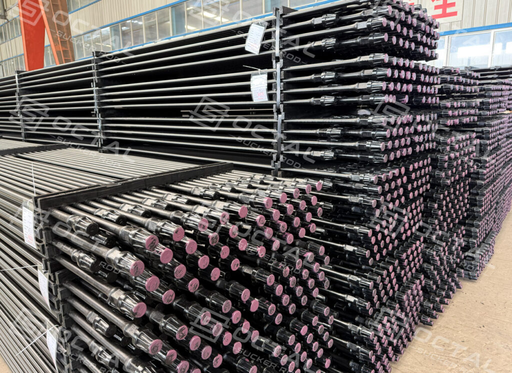
API 11B Sucker Rod Sizes and Pin Matching
The rod-body diameter and pin size must be treated as a matched configuration. A replacement rod selected only by body diameter can create an incompatible connection at the wellsite.
| Nominal rod-body diameter | Metric diameter | Typical API pin size |
|---|---|---|
| 5/8 in. | 15.88 mm | 15/16 in. |
| 3/4 in. | 19.05 mm | 1 1/16 in. |
| 7/8 in. | 22.23 mm | 1 3/16 in. |
| 1 in. | 25.40 mm | 1 3/8 in. |
| 1 1/8 in. | 28.58 mm | 1 9/16 in. |
The larger forged end and pin carry the connection load while the shoulder provides the controlled bearing surface after correct make-up. Pin diameter, thread form, shoulder condition and coupling size should therefore be checked together.
Standard steel sucker rod-body sizes normally stop at 1 1/8 in. Larger dimensions shown in a general rod-lift catalogue may refer to polished rods, sinker bars or fiberglass rod products.
API 11B Sucker Rod Grades
API rod grades describe a material and performance class. They do not automatically identify one fixed AISI chemistry or one identical manufacturing route across every mill.
| Grade family | Typical material route | Minimum yield strength | Tensile strength range | General selection position |
|---|---|---|---|---|
| C | Carbon steel | 60 ksi / 414 MPa | 90–115 ksi / 621–793 MPa | Light-to-moderate loading in controlled service |
| K | Alloy steel | 60 ksi / 414 MPa | 90–115 ksi / 621–793 MPa | Moderate loading where the approved K-grade metallurgy suits the fluid environment |
| DC, DA, DS | Carbon, alloy or special-alloy D-strength classes | 85 ksi / 586 MPa | 115–140 ksi / 793–965 MPa | Medium-to-heavy rod loads and deeper rod strings |
| HA, HS | Alloy or special-alloy high-strength classes | 115 ksi / 793 MPa | 140–155 ksi / 965–1,069 MPa | Deep wells and high-load positions after fatigue and corrosion review |
These figures are grade-family reference values. The ordered API edition, manufacturer’s MPS and purchase-order acceptance criteria remain controlling.
Commercial descriptions such as D, KD, HL or HY still appear in the market. They should be translated into the exact material class, mechanical-property range, chemistry route, heat treatment and product marking required for the order. A legacy name or paint color is not sufficient for material acceptance.
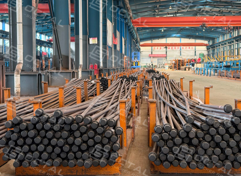
Selecting Rod Grade and Diameter
Rod-string loading
Rod-body size should be determined from the complete rod-string design. The calculation normally considers rod weight in fluid, pump load, dynamic acceleration, peak polished-rod load, minimum load, stress range, stroke length, pumping speed and the position of each rod section in a tapered string.
A high-strength grade can increase allowable load, but it does not correct an undersized connection, poor taper design or excessive cyclic stress.
Corrosion environment
Produced water, CO₂, H₂S, chlorides, oxygen entry and chemical treatment history should be reviewed together. Higher tensile strength does not automatically provide higher corrosion resistance, and corrosion pits can become fatigue-crack initiation sites under cyclic loading.
The enquiry should state the available water analysis, gas composition, temperature, inhibitor program and previous rod-failure history. Material selection can then be aligned with the actual service environment.
Well deviation and tubing contact
In deviated wells, rod bending and rod-to-tubing contact may control service life before the nominal axial strength is reached. Dogleg severity, tubing size, coupling outside diameter, rod guides and expected wear locations should be included in the design review.
Slim-hole couplings can improve clearance, but their strength, material class and make-up requirements must remain compatible with the rod string.
Reciprocating and rotary service
API sucker rods are commonly specified for reciprocating rod-pump systems. Progressing cavity pump applications introduce torsional loading in addition to axial stress. The proposed rod, pin and coupling configuration should have documented suitability for the expected torque, rotation direction, speed and connection make-up procedure.
Manufacturing Process
Production begins with heat-identified steel bar selected to the required API class and approved manufacturing specification. Chemical composition is verified against the applicable material route before the bar enters rod production.
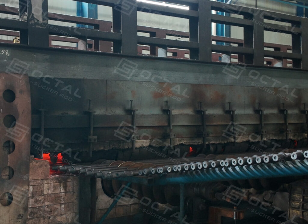
The rod ends are heated and forged to form the upset transition, wrench flats and pin section. The transition between the rod body and forged end is fatigue-sensitive, so laps, folds, surface tearing and abrupt profile changes require close control.
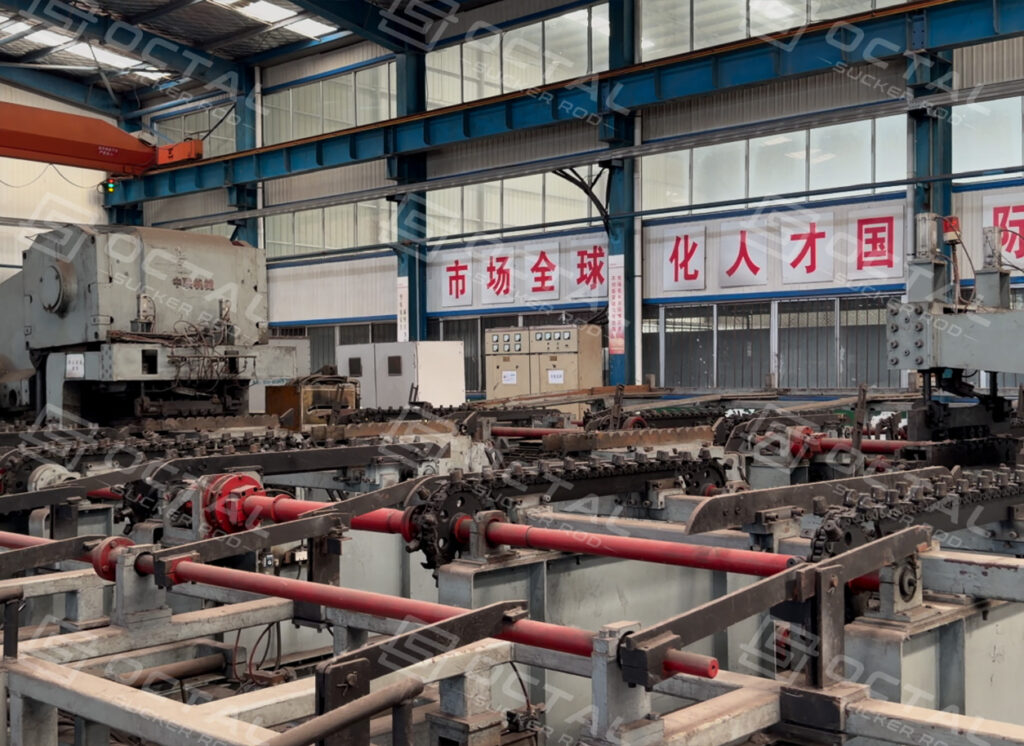
Heat treatment is performed according to the grade and qualified manufacturing route. Normalize-and-temper or quench-and-temper processes may be used depending on the material class. Furnace charts, heat-treatment lots and mechanical-test specimens should remain linked to the original steel heat.
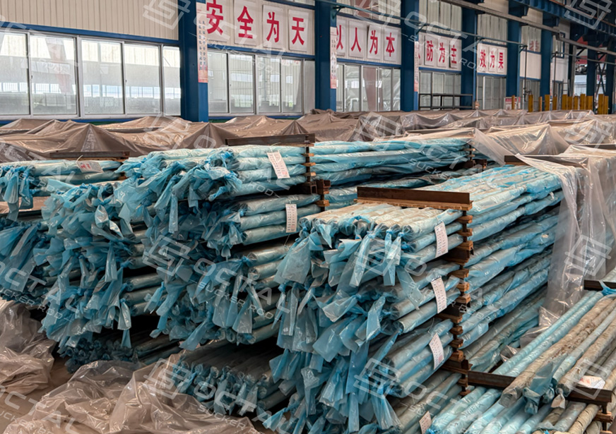
After heat treatment, the rod is straightened and the pin, thread relief and shoulder are machined. Working gauges are used to verify the connection. The completed rod is inspected, marked, protected and packed by identifiable heat or production lot.
Shot peening, induction hardening, special coatings and other fatigue or corrosion treatments should be described as manufacturer-specific options.
Inspection and Traceability
| Inspection Stage | Acceptance Focus | Typical Verification |
|---|---|---|
| Steel heat and chemistry | Chemical composition and material grade identification | Heat analysis, MTC and heat-number traceability |
| Forged ends | Upset profile, wrench flat, surface condition and forging defects | Visual inspection, dimensional check and specified NDE such as MPI where required |
| Heat treatment | Qualified heat-treatment cycle and hardness control | Furnace chart, production lot record and mechanical test specimens |
| Mechanical testing | Yield strength, tensile strength, elongation and reduction of area according to grade | Tensile test results matched with the applicable API 11B grade |
| Rod body dimensions | Diameter, length, straightness and surface condition | Diameter range 5/8 in. to 1-1/8 in., standard lengths 25 ft and 30 ft, dimensional inspection report |
| Pin and shoulder inspection | Pin diameter, thread form, shoulder condition and gauge acceptance | Thread gauge report and connection inspection record |
| Coupling compatibility | Matching rod pin size, coupling type and material class | Connection verification before assembly or shipment |
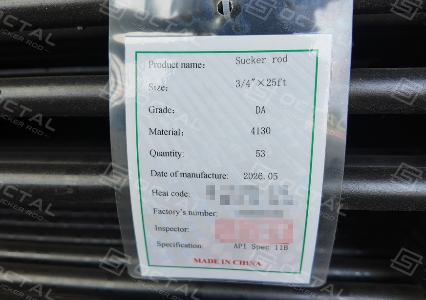
| Final traceability | Marking, heat number, grade and production lot identification | MTC, inspection records and packing-list traceability |
Critical projects may specify 100% finished-rod visual and dimensional inspection, 100% pin gauging, magnetic-particle testing of forged end areas, or full-length EMI/UT of the rod body. Required methods, coverage, sampling frequency and acceptance criteria should be written into the purchase order or inspection and test plan.
Sucker Rod Connections and Couplings
The coupling is part of the load path. It should be selected with the rod pin size, material class, tubing clearance and operating load already defined.
Full-size couplings provide the standard connection envelope. Slim-hole couplings reduce outside diameter where tubing clearance or rod-to-tubing contact is a concern. Class T, spray-metal and other coupling options address different combinations of wear, corrosion and strength requirements.
Connection release should confirm:
• Correct rod pin and coupling size
• Thread and shoulder condition
• Results from calibrated API working gauges
• Coupling material class and heat-treatment traceability
• Required thread-surface treatment
• Approved thread compound and make-up procedure
• Clean, correctly fitted thread protectors
For available configurations, see sucker rod couplings.
Sucker Rod Selection Considerations
Deep or tapered rod strings
The upper section of a deep rod string carries the suspended weight of the rods below it together with the dynamic pump load. Larger diameters or higher-strength classes may be required in the upper taper, while smaller rods can be used lower in the string after stress and fatigue calculations are completed.
Deviated wells
Doglegs increase bending stress and sliding contact. Selection should consider rod guides, coupling outside diameter, tubing wear, polished-rod alignment and previous failure locations. A change in grade alone may leave the contact mechanism unchanged.
Corrosive produced fluids
CO₂, H₂S, chlorides and water can promote pitting, hydrogen-related damage or general metal loss. Rod material, surface condition, inhibitor treatment and inspection interval should be selected as one corrosion-control program.
Replacement and workover stock
Replacement rods must match the installed pin and coupling system. Before mixing new and existing components, confirm nominal sizes, connection geometry, material class, API edition, shoulder condition and remaining service condition.
Why Choose Octal Suckerod
Octal supports sucker rod projects with clear technical coordination from specification review through production and shipment. Where requirements are incomplete or inconsistent, our team checks the details with the customer before production rather than leaving mismatches to be resolved at the delivery stage.
For replacement and repeat orders, previous markings, drawings and packing records can be reviewed to keep the new supply consistent with the existing rod string. Product recommendations are based on the actual well conditions and required service performance, without adding unnecessary grades, treatments or configurations.
FAQ
Q1:Is a proprietary high-strength sucker rod grade equivalent to an API 11B class?
A1:No automatic equivalence should be assumed. Compare the specified yield and tensile limits, heat-treatment route, connection capacity, fatigue or corrosion qualification, inspection requirements and manufacturer’s product specification before approving a substitution.
Q2:Can API 11B sucker rods from different manufacturers be used in the same rod string?
A2:They may be compatible when the pin size, coupling dimensions, thread gauging, material class and load capacity are confirmed. Proprietary high-strength rods or special connections require a separate compatibility review before being mixed with an existing string.
Q3:What should be agreed before third-party inspection of API 11B sucker rods?
A3:The purchase order or ITP should define the inspection stage, sampling level, test method, acceptance criteria and witness points before production begins. This gives the inspector a clear basis for releasing the rods and reviewing the final documentation.
Q4:What information is needed to investigate a premature API 11B sucker rod failure?
Preserve the failed section and adjacent connections without cleaning the fracture surface. Record its position in the rod string, operating time, load data, well conditions and clear photographs. These details help determine whether the failure originated from overload, fatigue, corrosion, bending or connection damage.