
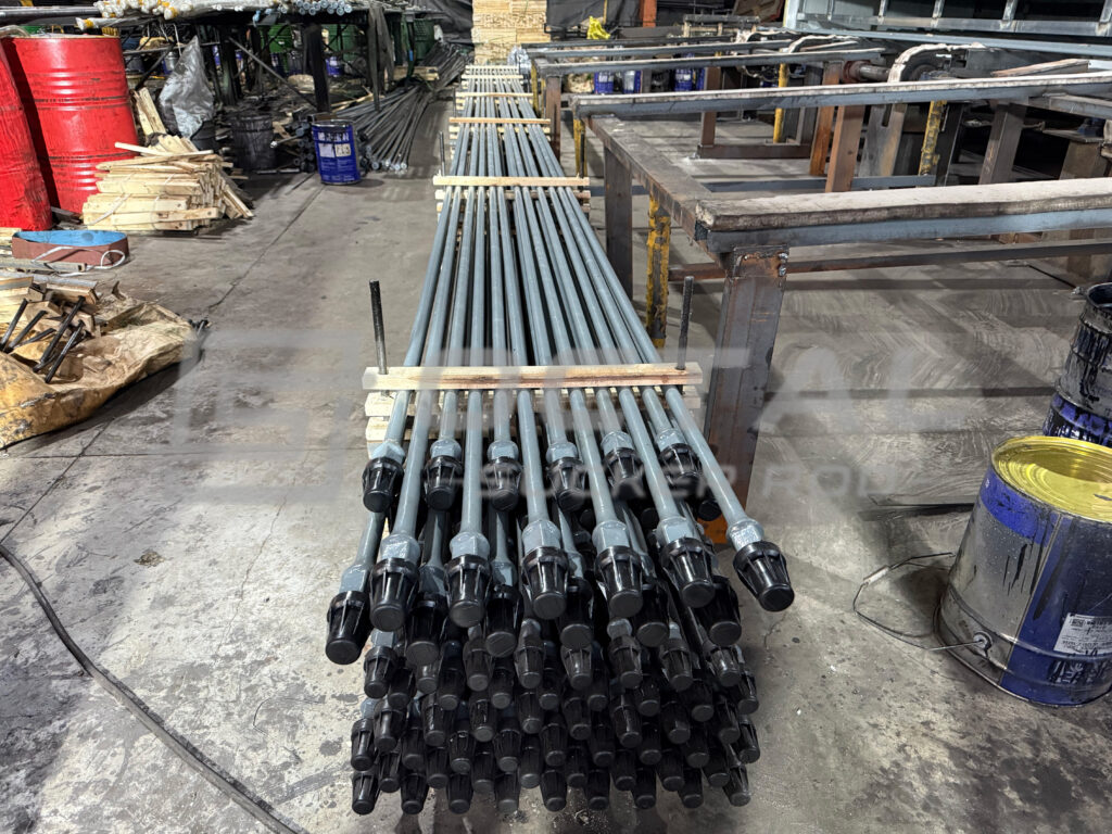
Sucker rods are slender, solid steel rods commonly supplied in 5/8 in to 1-1/4 in rod-body diameters and standard lengths of 25 ft and 30 ft, with dimensional and connection requirements generally specified to API Spec 11B. Conventional steel rods are produced from round bar, with both ends locally upset or forged, machined with wrench flats and shoulders, and threaded for connection by sucker rod couplings. Individual rods are assembled end to end to form the complete rod string. Octal supplies multiple diameters, grades and connection configurations, with matched couplings and related rod-string components available for complete-string and replacement requirements.
During operation, the surface pumping unit drives the polished rod and sucker rod string in reciprocating motion, transmitting axial load and movement to the downhole rod pump. Sucker rods are widely used in conventional rod-pumped oil wells, deep wells, high-load pumping systems and deviated wells, where reliable cyclic motion transfer is required. The rod itself does not carry produced fluid; the downhole pump performs the fluid lifting, while the rod string provides the mechanical drive. Rod diameter, grade, connection, tubing clearance and string configuration are selected together according to well depth, pump load and actual service conditions.
Sucker Rod Specifications and Sizes
API Spec 11B defines the principal dimensional, material, connection and performance requirements for sucker rods used in rod pumping systems. A complete sucker rod specification normally includes the rod material or grade, nominal rod-body diameter, standard length, pin connection and compatible coupling configuration.
Rod size should not be considered as a dimensional value alone. The selected diameter changes the rod cross-sectional area, rod-string weight and available clearance inside the tubing, while the grade determines the mechanical strength available for the expected operating load. For this reason, sucker rod size, grade and connection need to be evaluated together for the intended well condition.
| Specification Item | Typical Sucker Rod Requirement |
|---|---|
| Product | Sucker Rod |
| Standard | API Spec 11B |
| Main Construction | Solid steel rod body with forged and threaded ends |
| Common Rod-Body Sizes | 5/8 in, 3/4 in, 7/8 in, 1 in, 1-1/8 in |
| Additional Size | 1-1/4 in |
| Standard Rod Length | 25 ft (7.62 m), 30 ft (9.14 m) |
| Typical Grades | C, K, D, KD, HL, HY |
| Connection | Shouldered sucker rod pin with matched coupling |
| Rod-String Use | Reciprocating rod lift and sucker rod pumping systems |
| Related Components | Couplings, pony rods, polished rods, sinker bars and sucker rod guides |
Sucker rod sizes from 5/8 in to 1-1/4 in cover the common rod-body diameter range used in conventional rod pumping systems. Smaller diameters reduce rod-string weight, while larger diameters provide more cross-sectional area for carrying axial load. Final size selection should also consider tubing clearance, coupling OD and the accumulated load carried by each rod-string section.
Common Sucker Rod Diameters
Rod diameter directly affects the axial stress in the rod body because nominal axial stress is calculated by dividing the applied axial load by the rod cross-sectional area. Under the same axial load, a larger rod diameter provides more cross-sectional area and therefore lowers the nominal stress carried by the rod body. Increasing diameter also adds rod-string weight and reduces the available clearance inside the tubing, so diameter selection must balance load capacity, total string weight and tubing space.
| Nominal Rod Size | Rod Body Diameter | Nominal Cross-Sectional Area | Illustrative Nominal Stress at 10 klbf Axial Load* | Typical Selection Consideration |
|---|---|---|---|---|
| 5/8 in | 15.88 mm | 0.307 in² / 198 mm² | 32.6 ksi | Lower rod weight but higher nominal stress for the same load |
| 3/4 in | 19.05 mm | 0.442 in² / 285 mm² | 22.6 ksi | Common smaller/intermediate rod-string size |
| 7/8 in | 22.23 mm | 0.601 in² / 388 mm² | 16.6 ksi | Widely used balance between area, weight and clearance |
| 1 in | 25.40 mm | 0.785 in² / 507 mm² | 12.7 ksi | Greater section area for higher sectional load |
| 1-1/8 in | 28.58 mm | 0.994 in² / 641 mm² | 10.1 ksi | Larger section where higher rod-body capacity is required |
| 1-1/4 in | 31.75 mm | 1.227 in² / 792 mm² | 8.1 ksi | Larger rod option; availability depends on grade and product design |
Sucker Rod Stock and Availability
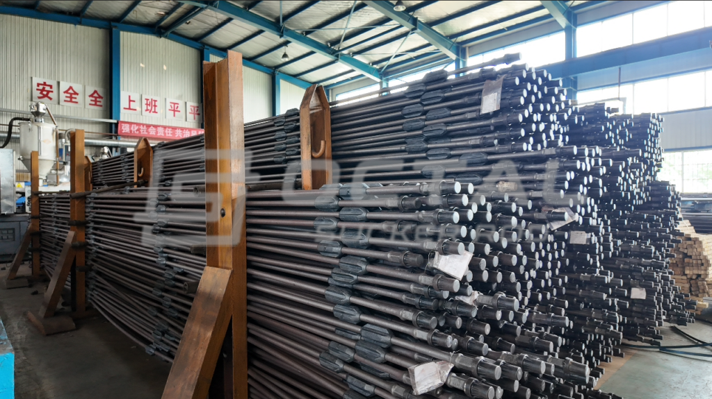
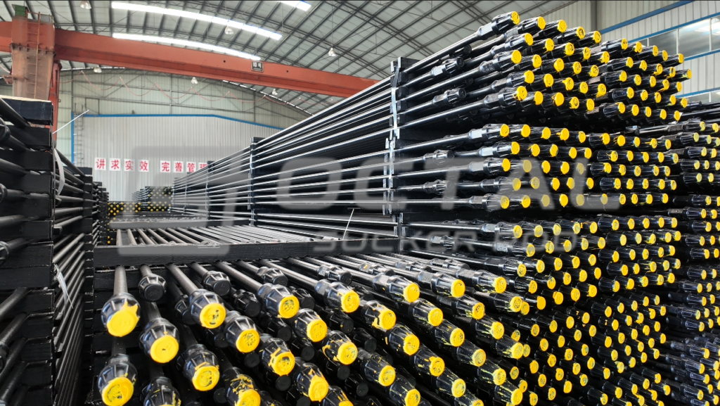
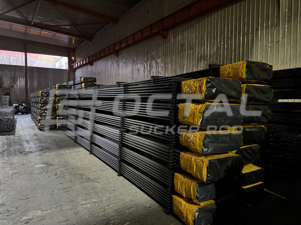
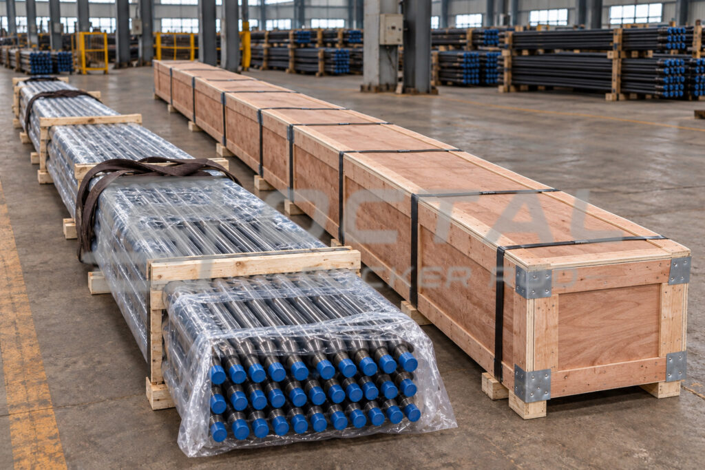
Octal maintains selected sucker rod sizes, grades and standard lengths for project supply and replacement requirements. Stock is managed by complete rod configuration, including rod diameter, grade, length and connection type. Standard 25 ft and 30 ft rods can be supplied with matched sucker rod couplings, while additional grade and connection combinations can be scheduled according to project requirements.
| Rod Size | Grade | Standard Length | Coupling / Connection | Example Quantity (pcs) |
|---|---|---|---|---|
| 5/8 in | Grade C | 25 ft | Matched sucker rod coupling | 1,860 |
| 3/4 in | Grade D | 25 ft | Matched sucker rod coupling | 2,450 |
| 7/8 in | Grade D | 25 ft | Full-size sucker rod coupling | 3,180 |
| 7/8 in | Grade HL | 30 ft | Full-size sucker rod coupling | 1,420 |
| 1 in | Grade D | 30 ft | Matched sucker rod coupling | 2,260 |
| 1 in | Grade HL | 30 ft | Matched sucker rod coupling | 1,180 |
| 1-1/8 in | Grade HL | 30 ft | Specified sucker rod coupling | 760 |
| 1-1/4 in | Project-specified grade | 30 ft | Connection to be confirmed | 420 |
In actual field applications, sucker rod availability and interchangeability should be evaluated by the complete rod configuration rather than by rod-body size alone. Grade, rod length, pin connection, coupling type and compatibility with the existing rod string all need to remain consistent, especially when several rod sizes or a tapered string configuration are used in the same well.
Types of Sucker Rods
Sucker rods are available in several construction forms to suit different rod-pumping conditions. Conventional steel sucker rods are widely used because they provide high stiffness, reliable threaded connections and a broad range of grade and diameter options. Fiberglass sucker rods are used where lower rod-string weight or improved corrosion resistance is required, while continuous sucker rods reduce the number of intermediate couplings in the string and are applied with specialized running and service equipment.
| Sucker Rod Type | Basic Construction | Main Engineering Characteristic | Important Selection Point |
|---|---|---|---|
| Steel Sucker Rod | Solid steel rod body with formed/forged ends and threaded connections | High stiffness and established API rod-lift connection system | Load, grade, fatigue, corrosion and tubing clearance |
| Fiberglass Sucker Rod | Fiber-reinforced composite body with metallic end connections | Lower unit weight and good resistance to many corrosive environments | Tensile/compression behavior, end fitting and well condition |
| Continuous Sucker Rod | Long continuous steel rod instead of conventional jointed 25/30 ft rods | Greatly reduces the number of intermediate couplings | Special running equipment, well geometry and service program |
Steel Sucker Rod
A steel sucker rod is the conventional choice for most rod pumping systems. It uses a solid steel rod body with forged or upset ends, wrench flats, threaded pins and couplings, giving the string high stiffness and a well-established connection system. Compared with fiberglass and continuous rods, steel rods are easier to configure by diameter and grade, and they can be combined into uniform or tapered rod strings according to the calculated load distribution.
Its main engineering trade-off is weight. Steel provides reliable tensile capacity and connection strength, but a deeper steel rod string also adds more suspended weight to the upper sections. Selection therefore focuses on rod diameter, grade, fatigue resistance, corrosion condition and tubing clearance.
Fiberglass Sucker Rod
A fiberglass sucker rod uses a fiber-reinforced composite rod body with metallic end fittings. Its main difference from a steel sucker rod is much lower rod weight and a different corrosion response, which can reduce the accumulated suspended load in deep wells and improve suitability for some corrosive service conditions.
Fiberglass rods are also more flexible than steel rods and behave differently under tensile and compressive loading. They cannot be selected as a direct one-for-one replacement for steel rods; elastic behavior, end-fitting design, load distribution and operating conditions must be considered when they are included in a rod string.
Continuous Sucker Rod
A continuous sucker rod is supplied as a long continuous rod rather than as many 25 ft or 30 ft jointed rods connected by couplings. Its main advantage is the large reduction in intermediate connections, which decreases the number of coupling contact points and eliminates repeated make-up between conventional rod joints.
Unlike standard steel or fiberglass jointed rods, continuous rod requires dedicated handling, running and service equipment. Its suitability therefore depends more strongly on well geometry, installation method, surface handling capability and maintenance strategy, rather than only on rod grade and nominal diameter.
Sucker Rod Grades and Mechanical Properties
Sucker rod grade defines the mechanical property range and material condition available to carry the applied rod-string load. In design, rod diameter and grade serve different functions: diameter determines the cross-sectional area and the nominal axial stress produced by a given load, while grade provides the yield strength, tensile strength and ductility margin required to sustain that stress through repeated pumping cycles. Grade selection therefore needs to reflect the calculated load level, service environment and rod-string configuration rather than being treated as an independent strength designation.
Typical Sucker Rod Grades
Steel sucker rods are available in different grades to match the load level and service condition of the rod string. Conventional grades provide sufficient strength for normal rod-pumping loads, while alloy and high-strength grades increase the available mechanical margin for deeper wells, heavier pump loads and more demanding cyclic service. Grade selection should consider both the calculated rod-string stress and the operating environment rather than tensile strength alone.
| Grade / Grade Family | Typical Mechanical Properties | Material / Treatment Characteristic | Typical Service |
|---|---|---|---|
| Grade C | Yield strength ≥ 90 ksi; tensile strength 100–115 ksi | Carbon-steel grade with controlled heat treatment | Conventional rod-pumping service with moderate loading |
| Grade D / DA | Yield strength about 100 ksi minimum; tensile strength 115–140 ksi | Alloy-steel grade, commonly normalized/tempered or quenched/tempered depending on product design | Medium to higher rod-string loads |
| KD / DS | Higher-strength alloy grade; property limits depend on the qualified material route | Ni-Cr-Mo or other alloy-steel systems designed for improved toughness and service performance | Medium-load wells where fatigue and corrosion conditions require additional margin |
| HA / HS | Tensile strength typically 140–155 ksi; minimum yield strength generally 115 ksi or higher depending on class | High-strength alloy steel with controlled heat treatment | Deep wells and high-load rod strings |
| HY | High-strength case-hardened design | Induction-hardened surface with a tougher core | Very high-load and severe cyclic service where a qualified HY design is specified |
Grade C is normally used where the rod string does not require a high-strength alloy grade. Grade D and KD move into higher-strength alloy-steel designs, while HA, HS and HY grades are intended for progressively higher mechanical demand. The correct grade still depends on rod diameter, calculated load, well depth, corrosion condition and the position of the rod within the string; a higher grade does not replace the need for correct rod-size and connection selection.
For sucker rod selection, tensile strength alone is not enough to define service capability. Yield strength determines the margin before permanent deformation, while elongation and reduction of area indicate the material’s ability to deform before fracture. In cyclic rod-pumping service, fatigue resistance is equally important because the rod string is subjected to repeated tensile loading throughout operation.
Sucker Rod Manufacturing and Working Principle
How Are Steel Sucker Rods Manufactured?
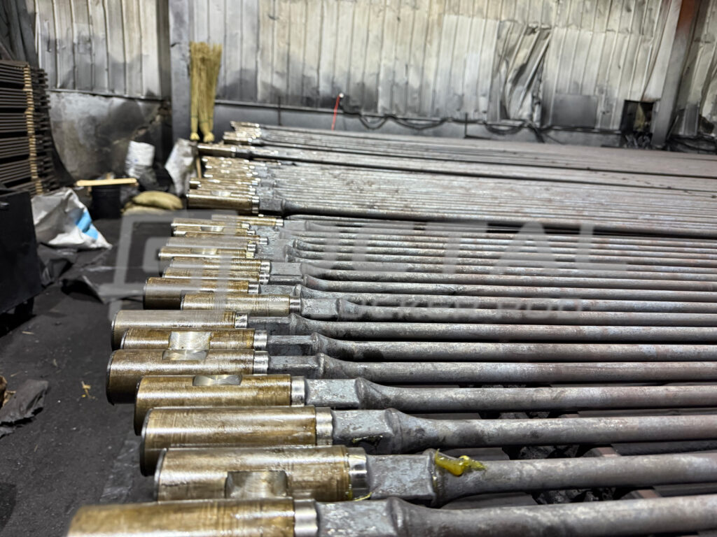
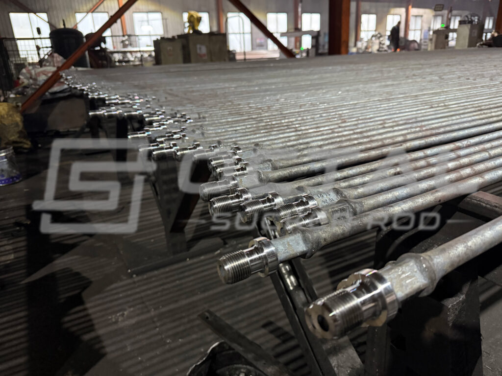
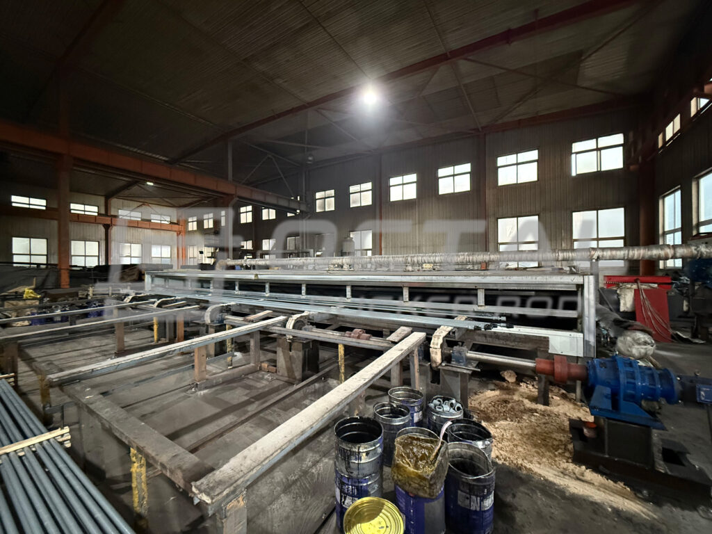
Steel sucker rod production starts with round steel bar selected to meet the chemistry and mechanical-property requirements of the specified grade. After the bar is cut to rod length, both ends are locally heated and upset-forged to create the enlarged rod-end section used for the pin shoulder, wrench flats and threaded connection, while the long central rod body remains slender and solid. The forged rod is then heat treated to develop the required strength and toughness, straightened to control full-length alignment, and finished at both ends by machining the shoulder and wrench flats and forming or machining the pin threads. Final dimensional, straightness and thread checks confirm that the rod body and connection geometry are suitable for assembly into the sucker rod string.
A typical manufacturing sequence is:
Steel Bar Preparation → Rod-End Forging → Heat Treatment → Straightening → Rod-End Machining → Thread Processing → Final Inspection and Protection
| Manufacturing Stage | Main Control | Engineering Purpose |
|---|---|---|
| Steel Bar Preparation | Material chemistry, rod-body diameter and surface condition | Establish the material basis for the required grade and mechanical properties |
| Rod-End Forging | Upset size, forged-end geometry and transition profile | Form the enlarged connection end while maintaining a smooth transition into the slender rod body |
| Heat Treatment | Temperature cycle and final material condition | Develop the required combination of strength, toughness and fatigue resistance |
| Straightening | Full-length rod alignment | Control bending and reduce unnecessary rod-to-tubing contact during reciprocating operation |
| Rod-End Machining | Pin shoulder, wrench flats and end dimensions | Establish the geometry required for connection make-up and handling |
| Thread Processing | Thread form, pitch, dimensions and surface condition | Produce a compatible pin connection capable of transferring cyclic load through the coupling |
| Final Inspection and Protection | Dimensions, straightness, thread gauging, surface condition and end protection | Verify the finished rod before storage, transportation and field assembly |
The rod-end transition deserves particular attention because the load carried by the long rod body must pass into a larger forged connection section before reaching the threaded pin and coupling. A smooth transition, accurate pin geometry and controlled thread dimensions help maintain a continuous load path through the assembled sucker rod string. Heat treatment and straightness control, meanwhile, determine how consistently the rod body responds to the repeated tensile loading generated during pumping.
How Does a Sucker Rod Pumping System Work?
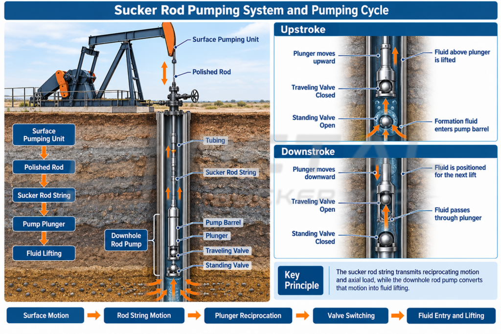
In a conventional rod pumping system, the surface pumping unit converts rotary drive into an up-and-down motion. This movement passes through the polished rod to the sucker rod string, which runs inside the tubing and connects to the plunger of the downhole rod pump. As the rod string reciprocates, it drives the pump plunger through repeated pumping cycles.
The downhole pump normally works with a traveling valve in the moving plunger and a standing valve near the bottom of the pump barrel. These two valves open and close in sequence as the plunger moves, allowing formation fluid to enter the pump barrel and then move upward into the tubing. The sucker rod itself does not carry produced fluid; it provides the mechanical motion and load required to operate the downhole pump.
The pumping cycle is divided into two basic stages: the upstroke and the downstroke. During each stroke, the traveling valve and standing valve change position to control fluid entry and upward movement through the pump.
Upstroke
During the upstroke, the surface unit pulls the polished rod and sucker rod string upward, causing the pump plunger to rise. The traveling valve remains closed, so the fluid above the plunger is lifted upward through the tubing. At the same time, pressure below the rising plunger decreases, allowing the standing valve to open and formation fluid to enter the pump barrel.
Downstroke
During the downstroke, the rod string moves the plunger downward. The standing valve closes, preventing fluid in the pump barrel from flowing back into the formation. Pressure below the plunger then opens the traveling valve, allowing fluid to pass through the plunger into the space above it. On the next upstroke, this fluid is lifted farther upward.
Through continuous repetition of these two strokes, fluid is drawn into the pump barrel and progressively lifted through the tubing toward the surface.
Sucker Rod Connection Design and Coupling Dimensions
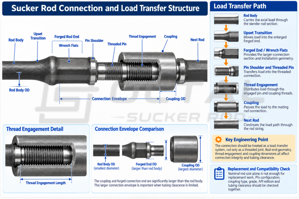
Individual sucker rods are connected end to end with threaded pins and sucker rod couplings to form the complete rod string. During operation, cyclic axial load is transferred continuously from the rod body through the upset transition, forged rod end, pin shoulder and threaded engagement into the coupling, and then into the next rod. Because the forged end and coupling have a larger outside diameter than the slender rod body, their dimensions directly affect tubing clearance and connection selection, especially in wells with restricted tubing ID or limited annular space.
Typical Full-Size Sucker Rod Coupling Dimensions
| Nominal Rod Size | Typical Full-Size Coupling OD | Typical Coupling Length |
|---|---|---|
| 5/8 in | 1.500 in / 38.10 mm | 4.0 in / 101.6 mm |
| 3/4 in | 1.625 in / 41.28 mm | 4.0 in / 101.6 mm |
| 7/8 in | 1.812 in / 46.0 mm | 4.0 in / 101.6 mm |
| 1 in | 2.187 in / 55.6 mm | 4.0 in / 101.6 mm |
| 1-1/8 in | 2.375 in / 60.33 mm | 4.5 in / 114.3 mm |
Full-size coupling OD increases with sucker rod size and becomes an important clearance limit inside the tubing. Where the available tubing ID is restricted, reduced-OD or slim-hole couplings may be used, but coupling size cannot be reduced without checking connection capacity and compatibility with the rod pin. For replacement or mixed rod-string applications, the rod size, thread configuration, coupling type, grade and available tubing clearance should be matched together to ensure that the connection can carry the required load without causing excessive rod or coupling contact with the tubing wall.
Sucker Rod String Configuration
A sucker rod string is designed according to the load carried at different depths rather than by applying one rod size or grade throughout the well. The upper section usually carries the highest accumulated tensile load because it supports the weight of the rods below together with the load transmitted from the downhole pump. As depth decreases toward the pump, the accumulated rod weight becomes lower, allowing the required rod diameter or grade to change by section. Rod-string configuration therefore has to balance sectional load, rod weight, fatigue demand, tubing clearance and connection capacity.
Uniform and Tapered Rod Strings
| Configuration | Rod Diameter / Grade | Main Characteristic | Appropriate Design Condition |
|---|---|---|---|
| Uniform Rod String | Same or substantially consistent specification through the selected string section | Simpler configuration | Where calculated loads and tubing clearance permit one rod specification |
| Tapered Rod String | Diameter and/or grade changes by depth section | Matches rod capacity more closely to changing sectional load | Deep or highly loaded wells where load varies significantly along the string |
A uniform rod string is easier to standardize, assemble and maintain because the same rod specification is used through the selected section. A tapered string can reduce unnecessary rod weight and lower the accumulated load carried by the upper string, but each change in rod size or grade introduces an additional transition that must be checked for coupling compatibility, connection capacity and tubing clearance. The final configuration therefore depends on whether the well benefits more from a simpler uniform layout or from the load and weight advantages of a tapered design.
How to Select Sucker Rods for Oil Wells
Sucker rod selection is based on the operating load and geometric limits of the complete rod-pumping system. Well depth and pump load determine the axial demand carried by the rod string, while tubing ID, well deviation, stroke, pumping speed, fluid condition and existing connection details influence the allowable rod diameter, grade and coupling configuration. These factors need to be evaluated together so that each rod-string section has sufficient load capacity, tubing clearance and fatigue margin for the actual service condition.
| Selection Input | Engineering Check | Effect on Sucker Rod Selection |
|---|---|---|
| Well Depth | Total rod-string length and accumulated suspended weight | Influences rod diameter, grade and need for tapering |
| Pump Setting Depth | Distance over which motion and load must be transmitted | Affects total string load and elastic behavior |
| Pump Size / Pump Load | Axial load transmitted through rod string | Determines required rod-body and connection capacity |
| Tubing Inside Diameter | Available radial space around rod and coupling | Limits maximum rod/coupling envelope |
| Stroke Length | Reciprocating displacement per cycle | Influences dynamic motion and fatigue exposure |
| Pumping Speed | Number of cycles over time | Influences fatigue demand |
| Well Deviation | Expected rod-to-tubing contact | Influences wear-control and sucker rod guide requirement |
| Produced Fluid | Water, CO₂, H₂S, chlorides and other corrosive constituents where present | Influences material/service-grade evaluation |
| Rod Grade | Mechanical strength and qualified material route | Determines available material strength margin |
| Rod Diameter | Cross-sectional area and rod-string weight | Changes nominal stress and accumulated string weight |
| Connection / Coupling | Thread fit, coupling OD and load capacity | Determines connection compatibility and tubing clearance |
| Existing Rod String | Legacy grade, connection and wear condition | Critical for replacement and partial-string orders |
Rod diameter, grade and string configuration should be adjusted according to the limiting condition identified from the well data. Excessive calculated stress may require a larger rod section where tubing clearance permits; insufficient material strength margin may require a higher-strength grade; and significant load variation with depth may favor a tapered rod string. Each adjustment must also be checked against coupling capacity, tubing ID and total rod-string weight so that improving one part of the design does not create a new limitation elsewhere in the system.
Sucker Rod vs Related Rod-String Components
A rod pumping system uses several rod-string components with different mechanical functions. The sucker rod forms the main load-transmitting string, while polished rods, pony rods, couplings, sinker bars, rod guides and the downhole pump each perform a specific role in connecting, adjusting, guiding or operating the system. Distinguishing these components is important when specifying replacements or configuring a complete rod string.
| Component | Main Function | How It Differs from a Standard Sucker Rod |
|---|---|---|
| Sucker Rod | Transmits reciprocating motion and axial load through the rod string | Main repeated rod-string component |
| Polished Rod | Forms the upper moving rod section through the wellhead sealing system | Requires a smooth external surface for stuffing-box sealing |
| Pony Rod | Adjusts total rod-string length | Shorter than standard 25/30 ft rods |
| Sucker Rod Coupling | Joins two threaded sucker rod pins | Female threaded connection component rather than a rod |
| Sinker Bar | Adds lower-string weight where required | Heavier/larger component used for rod-string dynamic control |
| Sucker Rod Guide | Controls rod-to-tubing contact | Wear-control accessory mounted on the rod string |
| Downhole Rod Pump | Converts rod motion into fluid displacement | Pumping device; it is not part of the load-transmitting rod itself |
These components are selected as part of the complete rod-pumping assembly rather than as interchangeable items. A pony rod adjusts string length, a polished rod provides the upper sealing and load-transfer section, a coupling connects adjacent sucker rods, and a rod guide controls rod-to-tubing contact. The downhole rod pump is the fluid-lifting component, while the sucker rod string provides the mechanical connection that drives it.
Applications of Sucker Rods
Sucker rod configuration changes with the mechanical and service conditions of the well. Conventional rod-pumped wells may use standard steel rod strings, while deeper wells, higher pump loads, frequent pumping cycles, well deviation or corrosive fluids place different demands on rod diameter, grade, string configuration, connection capacity and wear control.
| Operating Condition | Main Requirement | Typical Rod Selection Direction |
|---|---|---|
| Conventional Rod-Pumped Well | Stable reciprocating load transfer | Standard steel sucker rod; uniform or simple tapered string according to calculated load |
| Deep Well | Higher accumulated rod-string weight | Tapered steel rod string with larger diameter or higher-strength upper sections |
| High Pump-Load Well | Higher axial load | Larger-diameter and/or higher-strength steel sucker rod with adequate connection capacity |
| High-Cycle Pumping | Repeated cyclic stress | Rod grade with sufficient fatigue margin and controlled connection geometry |
| Deviated Well | Increased rod-to-tubing contact | Steel sucker rod with suitable guides; coupling OD and tubing clearance require additional checking |
| Corrosive Produced Fluid | Corrosion plus cyclic loading | Corrosion-resistant steel grade or fiberglass sucker rod where the service condition permits |
| Replacement Rod String | Compatibility with existing string | Match rod size, grade, thread, coupling and existing connection configuration |
These operating conditions often overlap in the same well, so the final sucker rod configuration is normally determined by the combined load and service requirements rather than by one condition alone. Deep or high-load wells may require larger-diameter or higher-strength rod sections, deviated wells place greater emphasis on tubing clearance and rod-guide control, while corrosive service may require a different material or rod type. Final rod size, grade, taper arrangement and connection should therefore follow the calculated rod-string load and actual well conditions.
Octal Sucker Rod Supply and Technical Support
Octal supplies sucker rods and related rod-string components for rod pumping and artificial lift applications. Supply can be coordinated by rod diameter, grade or material class, standard rod length, connection type and compatible coupling requirement. Related components such as pony rods, polished rods, sucker rod couplings and sucker rod guides can also be matched where a complete rod-string package is required.
Sucker rod configuration can be matched to well depth, tubing size, pump load, rod diameter, grade, connection type and service environment. Where a complete rod string is required, rod size, grade, coupling and related components can be coordinated as one system rather than selected independently. For replacement applications, the existing rod size, thread configuration, coupling type and rod-string arrangement should be checked together so that the new components remain compatible with the installed system.
FAQ
Can different sucker rod sizes and grades be used in the same rod string?
Yes. A tapered rod string can use different diameters and/or grades in different well sections. The upper section normally carries the highest accumulated load, while smaller or lower-strength rods may be used farther down the string where calculated load permits. Section length, coupling compatibility and tubing clearance should be checked together.
How do you check whether a sucker rod coupling will fit inside the tubing?
Compare the maximum coupling OD with the actual tubing ID and the available operating clearance, not just the sucker rod body diameter. Deviated wells require additional allowance because rod and coupling contact with the tubing wall can increase during reciprocating operation.
When should fiberglass sucker rods be considered instead of steel sucker rods?
Fiberglass sucker rods can be considered where reducing rod-string weight or improving resistance to corrosive fluids provides a clear benefit. Their lower stiffness and different compression behavior mean they should not be treated as a direct one-for-one replacement for steel rods; the complete rod-string load and operating condition must be recalculated.
Can a sucker rod be replaced simply by matching the same nominal diameter?
No. The replacement rod should also match the required grade, length, pin/thread configuration, coupling type and connection capacity. The existing tubing clearance and rod-string arrangement should also be checked, particularly when replacing only part of a mixed-size or tapered string.